Compact micro gas turbine

A micro gas turbine, compact technology, used in gas turbine devices, mechanical equipment, engine components, etc., can solve the problems of long distance, large volume, large airflow pressure loss, etc., and achieve the effect of high efficiency, small size, and shortened axial distance.

Active Publication Date: 2014-10-08
BEIHANG UNIV
View PDF4 Cites 16 Cited by
  • Summary
  • Abstract
  • Description
  • Claims
  • Application Information

AI Technical Summary

Problems solved by technology

Some micro gas turbines use a single-tube combustor, the distance from the compressor outlet to the combustor inlet is long and there are several deflections, the airflow pressure loss is large, and the volume is also large

Method used


Image

  • Compact micro gas turbine
  • Compact micro gas turbine
  • Compact micro gas turbine

Examples


Embodiment Construction

[0020] The present invention will be described in detail below with reference to the drawings and specific implementations.

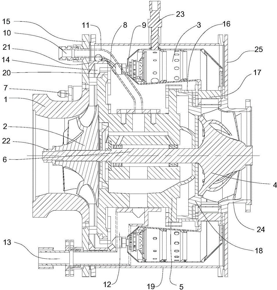
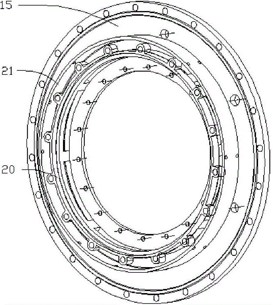
[0021] A micro gas turbine of this embodiment includes a compressor 2, a combustion chamber 3, a turbine 4, a shafting mounting body 5, a shaft 6 and a casing 19; the compressor 2 is a single-stage centrifugal compressor; the combustion chamber 3 is a full-circular combustion Chamber; Turbine 4 is a single-stage centripetal turbine; such as figure 1 As shown, the air inlet 1 and the front flange 15 are connected by screws and are installed at the front end of the compressor 2. The air enters the compressor through the air inlet 1; the diffuser inner ring 20 and the diffuser outer ring 21 are welded to the front On flange 15 (e.g. figure 2 (Shown), the diffuser inner ring 20 has bolt holes, the diffuser inner ring 20 is in clearance fit with the outer diameter of the front end of the shafting mounting body 5, and the shafting mounting body 5 is fixed into t...


PUM


Abstract

The invention discloses a compact micro gas turbine, which mainly comprises an air inlet channel, an air compressor, a combustion chamber, a turbine, a shaft system installing body, a shaft and a shell, wherein the air compressor is a single-stage centrifugal air compressor; the combustion chamber is a full ring combustion chamber; the turbine is a single-stage concentric turbine; the air inlet channel is connected with a front flange through a screw; an inner ring of a diffuser and an outer ring of the diffuser are welded on the front flange; the direction of air flow is changed from radial to axial after passing through the diffuser; the shaft system installing body is fixed in the inner ring of the diffuser; the turbine and the shaft are integrally machined; after the turbine shaft penetrates through the shaft system installing body, the air compressor is arranged at the front end of the turbine shaft and is locked through an air compressor wheel locking nut; the rear end of the shaft system installing body is connected with the installing plate of the turbine through screws; the rear end of installing plate of the turbine is fixed with the front end of a guider of the turbine; the combustion chamber is arranged outside the shaft system installing body and axially covers the front half part of the turbine; the direction of the air flow is changed from axial to radical after passing through the combustion chamber; the air flow impacts the turbine through the guider of the turbine; the guider of the turbine, the rear end of the combustion chamber and the shell of the turbine are collectively fixed with a rear flange.

Description

Technical field [0001] The invention relates to a gas turbine, in particular to a compact micro gas turbine. Background technique [0002] Micro gas turbine refers to a small-power gas turbine with a single engine power within hundreds of kilowatts. It can use natural gas, biogas, gasoline, diesel, and alkane gas as fuel. Micro gas turbines can be used as the core device of distributed energy technology to realize the efficient energy utilization of combined cooling, heating and power. Micro gas turbines can also be used in aviation, aerospace and other fields, as well as military vehicle auxiliary power devices, vehicle hybrid power devices, etc. [0003] The development of micro gas turbines abroad is relatively early. The United States, Japan and some European countries are all studying micro gas turbines and developing their application functions. Many products have entered the market now. In China, the micro gas turbine is a major special project in the energy technology fie...

Claims


Application Information

Patent Timeline
Patent Type & Authority Applications(China)
IPC IPC(8): F02C3/04F02C3/16F01D5/02
Inventor 林宇震王建臣许全宏张弛
Owner BEIHANG UNIV
Why Eureka
Try Eureka