Liquefied natural gas vaporizer and production device and method thereof
A technology of liquefied natural gas and vaporizer, which is applied in the direction of welding equipment, auxiliary welding equipment, metal processing equipment, etc., can solve the problems of affecting the service life of the heat exchanger, not being able to exchange heat with seawater, and not being able to conduct reasonable heat exchange with uniform standpipes, etc., to achieve increased Heat exchange efficiency, increase heat exchange capacity, and ensure the effect of service life
- Summary
- Abstract
- Description
- Claims
- Application Information
AI Technical Summary
Problems solved by technology
Method used
Image
Examples
Embodiment 1
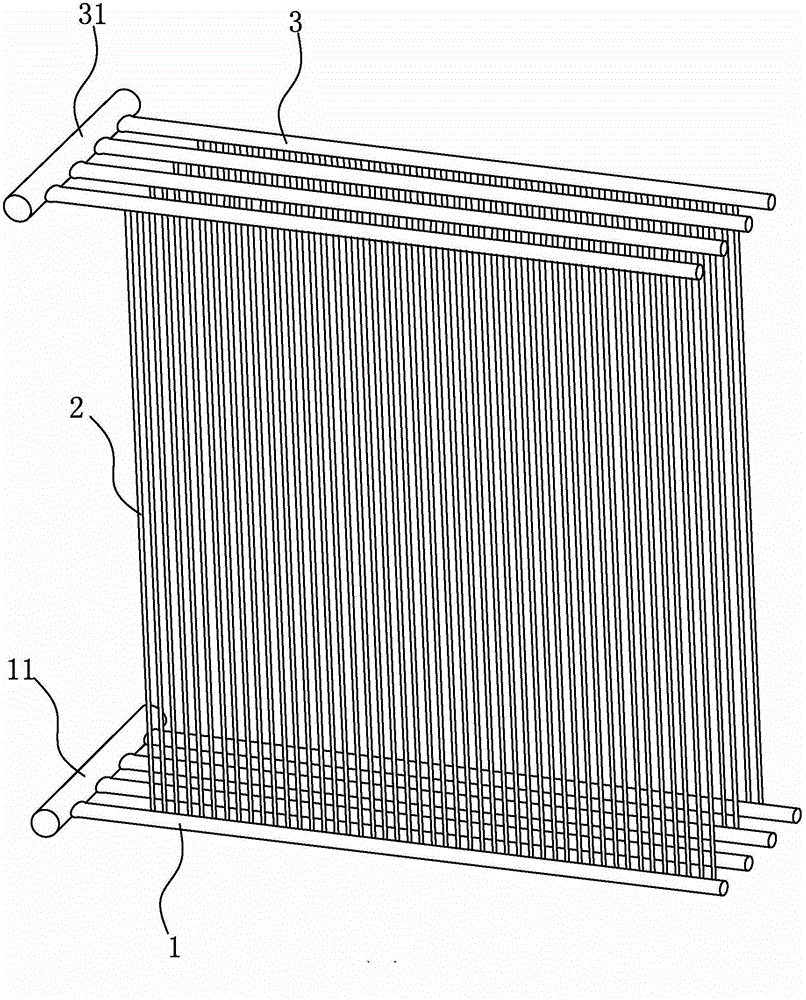
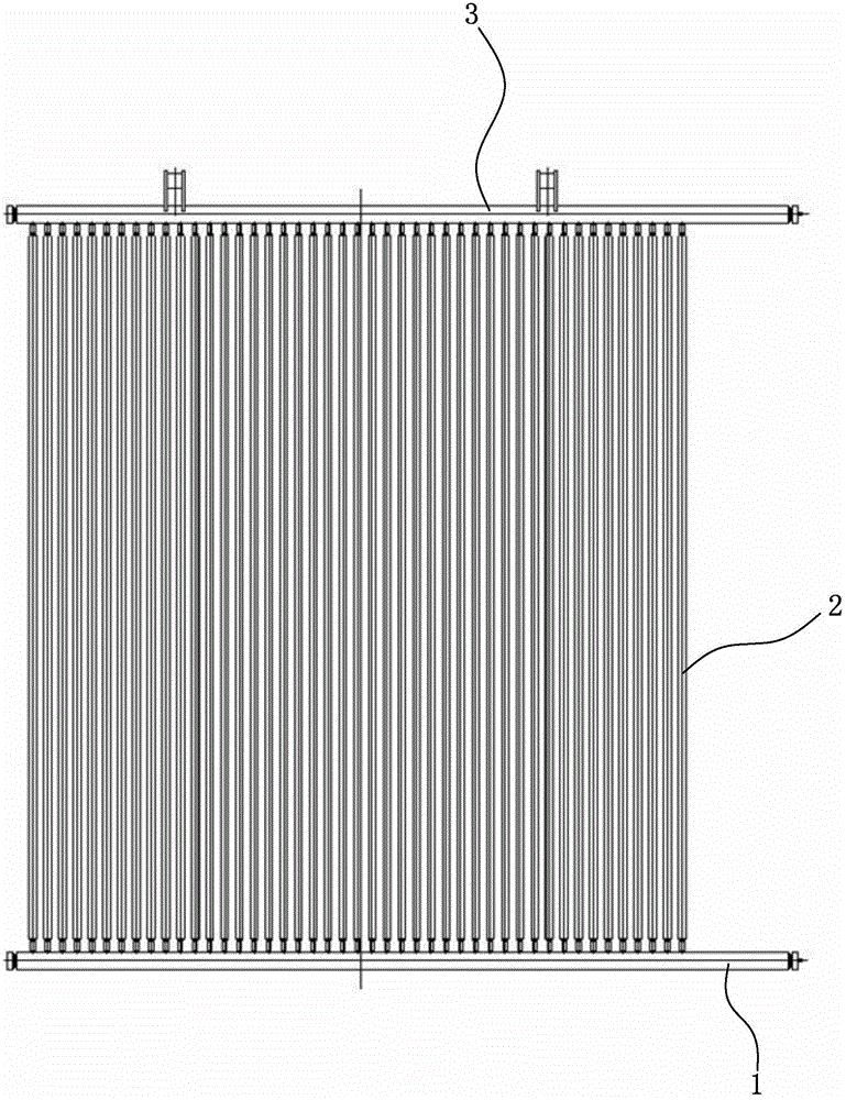
[0069] Such as Figure 1-19 shown, see figure 1 and figure 2 , a kind of liquefied natural gas vaporizer among the present invention, comprises lower transverse pipe 1, vertical pipe 2, upper transverse pipe 3, injection pipe 15 and cooling fin. The lower tube hole 131 of the lower horizontal tube 1 is welded and communicated with the bottom of the vertical tube 2 through the welded tube 20, and the top of the vertical tube 2 is welded and communicated with the upper tube hole 31 of the upper horizontal tube 3 through the welded tube 20. The upper horizontal tube 3 and the lower horizontal tube 1 are provided with a plurality of standpipes. The plurality of lower horizontal pipes 1 communicate with each other through the lower connecting pipe 11, and the lower connecting pipe 11 is used for flowing in liquid natural gas. The upper horizontal pipes 3 communicate with each other through the upper connecting pipe 31, and the upper connecting pipe 31 is used for air outlet.
...
Embodiment 2
[0082] Such as Figures 20-24 shown, see Figure 20, an integral welding tool for a liquefied natural gas vaporizer in the present invention, comprising a left plate 41 , a middle plate 42 and a right plate 43 . The left plate 41 and the right plate 43 are used to discharge the vertical pipes 2 (not shown) at equal intervals and weld a whole series of vertical pipes 2 with the fourth cooling fin 25, and weld the whole series of vertical pipes 2 placed on the middle board 42. The middle plate 42 is used to weld a whole series of vertical pipes 2 with the upper horizontal pipe 3 and the lower horizontal pipe 1 into one body.
[0083] Such as Figure 22 As shown, the right end of the left plate 41 is hingedly connected with the left end of the middle plate 42 , and the right end of the middle plate 42 is hingedly connected with the left end of the right plate 43 . The lower surface of the clamp 411 on the left plate is provided with U-shaped grooves at equal intervals, and th...
Embodiment 3
[0099] Such as Figure 25 and 26 shown, see Figure 25 , a perforated transport clamp for round pipes in the present invention, including a clamp connecting plate 51 and a quick clamp 52 . A plurality of quick clamps 52 are arranged on the clamp connecting plate 51 . A plurality of quick clamps 52 cooperate with the clamp connecting plate 51 to clamp the round tube 263 together to ensure that round tube holes 2631 are provided radially on the round tube 263 with a smaller diameter and longer length.
[0100] Such as Figure 26 As shown, the clamp connecting plate 51 is arranged in the left and right directions, and the front end of the clamp connecting plate 51 is provided with grooves along the left and right directions, and the shape of the groove matches the shape of the outer peripheral surface of the round tube 263 .
[0101] Such as Figure 26 As shown, the quick clamp 52 includes a lever 521 , a small connecting rod 522 , a vertical connecting rod 5231 , a horizont...
PUM
 Abstract
Description
Claims
Application Information
 - R&D
- Intellectual Property
- Life Sciences
- Materials
- Tech Scout
- Unparalleled Data Quality
- Higher Quality Content
- 60% Fewer Hallucinations
Browse by: Latest US Patents, China's latest patents, Technical Efficacy Thesaurus, Application Domain, Technology Topic, Popular Technical Reports.
© 2025 PatSnap. All rights reserved.Legal|Privacy policy|Modern Slavery Act Transparency Statement|Sitemap|About US| Contact US: help@patsnap.com


