Thermocouple insulation locator, mounting method thereof and wall temperature measuring device

A thermocouple and positioner technology, applied in the direction of measuring device, using electric device, measuring heat, etc., can solve the problems of thermocouple wire fatigue fracture, wire disconnection, shortening the service life of thermocouple, etc. Sensitive, mass-manufacturable, simple-structured effects

Inactive Publication Date: 2014-10-08
NUCLEAR POWER INSTITUTE OF CHINA
View PDF9 Cites 26 Cited by
  • Summary
  • Abstract
  • Description
  • Claims
  • Application Information

AI Technical Summary

Problems solved by technology

However, during use, the connection point between the thermocouple rear-end wire and the thermocouple front-end protection tube will bear the tension of the spring for a long time, which will easily cause the wire to be disconnected at the thermocouple rear-end connection point.
Especially when there is vibration in the device under test, the stretching length of the spring changes periodically, and the thermocouple wire and the front-end protection tube are prone to fatigue fractures, which greatly shortens the service life of the thermocouple.

Method used


Image

  • Thermocouple insulation locator, mounting method thereof and wall temperature measuring device
  • Thermocouple insulation locator, mounting method thereof and wall temperature measuring device
  • Thermocouple insulation locator, mounting method thereof and wall temperature measuring device

Examples


Embodiment 1

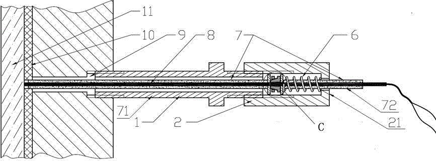
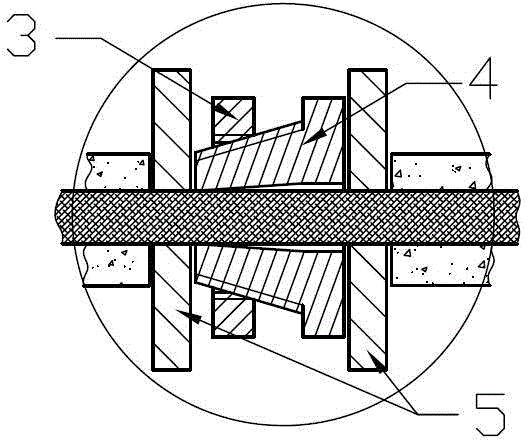
[0038] Such as figure 1 and figure 2 As shown, the thermocouple insulation positioner includes a positioning guide tube 1, a push nut 2, a positioning nut 3, a self-tightening positioning bolt 4, two insulating baffles 5, a pushing spring 6, and an insulating sleeve 7. The insulating sleeve The pipe 7 includes a first insulating sleeve 71 and a second insulating sleeve 72, wherein:

[0039] The center of the self-tightening positioning bolt 4 and the two insulating baffles 5 is provided with a through hole for the passage of the thermocouple 8, and the two insulating baffles 5 are respectively located at both ends of the self-tightening positioning bolt 4, and the thermocouple 8 passes through the insulation The baffle piece 5 and the self-tightening positioning bolt 4, the front end is penetrated in the first insulating sleeve 71 and the end extends out of the first insulating sleeve 71, and the rear end is penetrated in the second insulating sleeve 72, that is, the first i...

Embodiment 2

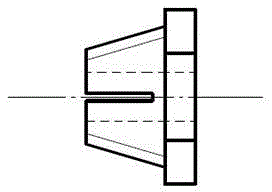
[0046] In this embodiment, on the basis of Embodiment 1, the self-tightening positioning bolt 4 is further improved, image 3 It is the front view of the self-tightening positioning bolt 4, the self-tightening positioning bolt 4 is a tapered bolt with a through hole, and its front end is a tapered thread segment. The above-mentioned groove is a strip groove, which is set on the tapered thread section at the front end of the tapered bolt. The length direction of the strip groove is parallel to the radial direction of the tapered bolt, and divides the end surface into two. The diameter of the through hole of the self-tightening positioning bolt 4 is slightly larger than the diameter of the thermocouple 8. When the positioning nut 3 is continuously screwed into the tapered thread section of the self-tightening positioning bolt 4, the diameter of the self-tightening positioning bolt 4 in the positioning nut 3 gradually increases. The increase makes the gap between the two sides of...

Embodiment 3

[0048] Such as Figure 4 As shown, on the basis of Embodiment 1 or Embodiment 2, in this embodiment, the rear end of the positioning guide tube 1 is also provided with a hexagonal head before pushing the nut 2, so as to facilitate the positioning between the front end of the guide tube 1 and the thermocouple channel 9. The threaded connection and disassembly between the space and the rear end and the push nut 2.

[0049] The outer tube wall at the front end of the positioning guide tube 1 is also provided with threads, so that the positioning guide tube 1 is screwed into the thermocouple channel 9, and the thermocouple can be disassembled and replaced after use.

[0050] The insulating sleeve 7 can be a ceramic tube, a quartz glass tube or a plastic tube, and the insulating baffle 5 can be a ceramic sheet, a quartz glass sheet or a plastic plate. In practical applications, the insulating sleeve 7 and the insulating baffle can also be made of Other insulating materials commonl...


PUM


Abstract

The invention discloses a thermocouple insulation locator, a mounting method of the locator and a wall temperature measuring device. The thermocouple insulation locator comprises a self-tightness locating bolt fixed to a thermal coupler, a locating nut connected to the self-tightness locating bolt, a first insulation casing pipe, a second insulation casing pipe, a locating guide pipe and a pushing and pressing nut, wherein the first insulation casing pipe and the second insulation casing pipe are arranged on the two sides of the self-tightness locating bolt and are arranged on the thermal coupler in a sleeved mode, the first insulation casing pipe is sleeved with the locating guide pipe, and the pushing and pressing nut is arranged on the second insulation casing pipe in a sleeved mode and is in threaded connection with the rear end of the locating guide pipe. An end cover is arranged at the rear end of the pushing and pressing nut, and insulation blocking pieces are arranged between the self-tightness locating bolt and the two insulation casing pipes, a pushing and pressing spring is arranged between the insulation blocking piece at the rear end of the self-tightness locating bolt and the end cover arranged at the rear end of the self-tightness locating bolt in a sleeved mode, and the second insulation casing pipe is sleeved with the pushing and pressing spring. According to the thermocouple insulation locator, the thermal coupler can be precisely located to the measuring point, it is ensured that the thermal coupler is insulated from other components except a measured device, and small vibration and migration of the measured device in the channel direction of the thermal coupler can be borne.

Description

technical field [0001] The invention relates to the technical field of heat pipe measurement, in particular to a thermocouple insulating positioner, an installation method thereof, and a wall temperature measuring device provided with the thermocouple insulating positioner. Background technique [0002] In a large number of industrial applications and scientific research experiments, it is necessary to measure and record the temperature in real time. Thermocouples have been widely used for their advantages of high precision, sensitive response and wide measurement range. Commonly used thermocouple measuring points are generally fixed by welding or mechanically. Welded mounts do not facilitate repositioning and re-use of thermocouples. And the conventional electric spark impact spot welding thermocouple will cause great damage to the surface condition and temperature field of the measured object, especially when the measured workpiece is small in size. For the device with ...

Claims


Application Information

Patent Timeline
Patent Type & Authority Applications(China)
IPC IPC(8): G01K7/02G01K1/14
Inventor 赵大卫熊万玉刘少波胡俊杨祖毛
Owner NUCLEAR POWER INSTITUTE OF CHINA
Why Eureka
Try Eureka