Coupler and manufacturing method thereof
A manufacturing method and coupler technology, which are applied to the coupling of optical waveguides and other directions, can solve problems such as unfavorable miniaturization of system modules and large volume of system modules, and achieve the effects of good stability, improved utilization, and uniform force.
- Summary
- Abstract
- Description
- Claims
- Application Information
AI Technical Summary
Problems solved by technology
Method used
Image

Examples
no. 1 example
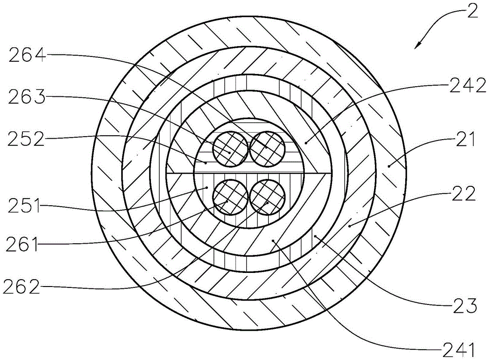
[0033] refer to image 3 and Figure 5 , image 3 is a cross-sectional view of coupler 2, Figure 5 is a schematic diagram of the structure of the coupler 2. The coupler 2 includes stainless steel tube 21 , silica gel 22 , heat shrinkable tube 23 , semicircular substrate 241 , semicircular substrate 242 , epoxy glue 251 , epoxy glue 252 , optical fiber 261 , optical fiber 262 , optical fiber 263 and optical fiber 264 . The semi-circular substrate 241 and the semi-circular substrate 242 are made of quartz material, and the semi-circular substrate 241 and the semi-circular substrate 242 are inversely fitted with each other to form the quartz substrate in this embodiment, and the optical fiber 261 and the optical fiber 262 form the first optical fiber assembly of this embodiment , the optical fiber 263 and the optical fiber 264 form the second optical fiber assembly of this embodiment, and the heat shrinkable tube 23 is used as the fixing tube of this embodiment.
[0034] ref...
no. 2 example
[0041] On the basis of the first embodiment of the coupler, in addition to using the heat-shrinkable tube 23 as the fixing tube of the first embodiment of the coupler, the fixing tube can also use a quartz tube to fix the semicircular substrates that are under-fitted with each other. Specifically, a quartz tube sleeve is provided, and the length of the quartz tube sleeve is greater than or equal to the quartz substrate. After the quartz tube is sleeved outside the quartz substrate, the dual-curing glue is used for heating and ultraviolet light, and finally forms a solidification, and then effectively The purpose of the present invention can be achieved by fixing the optical fiber assembly. The specific use method and principle of dual-cure adhesive can refer to the paper "Dual-dual-cure curing technology in U-V curing adhesives" published by Wang Tao, a master of Anhui University of Science and Technology in 2007 "Application Research in China".
[0042] Embodiment of coupler...
PUM
 Abstract
Description
Claims
Application Information
 - Generate Ideas
- Intellectual Property
- Life Sciences
- Materials
- Tech Scout
- Unparalleled Data Quality
- Higher Quality Content
- 60% Fewer Hallucinations
Browse by: Latest US Patents, China's latest patents, Technical Efficacy Thesaurus, Application Domain, Technology Topic, Popular Technical Reports.
© 2025 PatSnap. All rights reserved.Legal|Privacy policy|Modern Slavery Act Transparency Statement|Sitemap|About US| Contact US: help@patsnap.com