Steel bar circular bending tool

A steel bar and bending technology, which is applied in the field of steel bar circular bending tools, can solve problems such as low work efficiency, inability to guarantee dimensional accuracy, and large material loss, and achieve low production costs, improve work efficiency and bending quality, and facilitate The effect of the operation

Inactive Publication Date: 2014-10-15
CHINA FIRST METALLURGICAL GROUP
View PDF13 Cites 16 Cited by
  • Summary
  • Abstract
  • Description
  • Claims
  • Application Information

AI Technical Summary

Problems solved by technology

The stiffening stirrups used in cast-in-situ piles are usually circular, and the production of stiffening stirrups is usually done manually, that is, the workers bend the steel bars into a circle by hand, which not only reduces work efficiency, but also cannot guarantee dimensional accuracy , large loss of material

Method used


Image

  • Steel bar circular bending tool
  • Steel bar circular bending tool

Examples


Embodiment Construction

[0018] In order to better understand the present invention, the technical solutions of the present invention will be further described below in conjunction with the embodiments and the accompanying drawings.

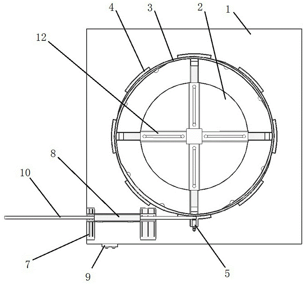
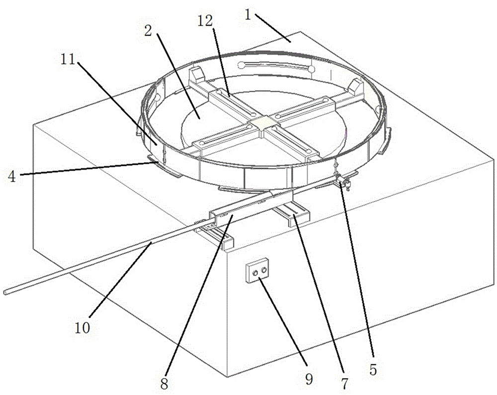
[0019] A circular bending tool for steel bars, characterized in that it includes a pedestal 1, a turntable 2 and a limit device, the turntable 2 and the limit device are installed on the pedestal 1, and the pedestal 1 is equipped with a 2 rotating driving device (the driving device is composed of a motor and a gearbox, the output end of the gearbox is connected to the center of the turntable 2, and the switch of the motor is set on the side of the pedestal 1); the turntable 2 is provided with a drum 3 (The rotating drum 3 and the rotating disc 2 have the same circle center), and the lower outer side of the rotating drum 3 is evenly provided with a plurality of supporting plates 4 along the circumferential direction (the supporting plates 4 are used to support the steel ba...


PUM


Abstract

The invention relates to steel bar bending equipment in the field of building engineering, in particular to a steel bar circular bending tool. The steel bar circular bending tool is characterized by comprising a pedestal, a rotating disk and a limiting device, wherein both the rotating disk and the limiting device are arranged on the pedestal; a driving device for driving the rotating disk to rotate is arranged inside the pedestal; a revolving drum is arranged on the rotating disk; a plurality of support plates are uniformly arranged on the outer side of the lower portion of the revolving drum along the circumferential direction; a fixing device for fixing a steel bar is arranged on one support plate; the limiting device is positioned on the side edge of the revolving drum, and is used for limiting the position of the steel bar. During use, the steel bar of which the position is limited is tangential to the outer wall of the revolving drum. By adopting the tool, the working efficiency during circular bending of the steel bar can be increased, and the bending quality can be improved.

Description

technical field [0001] The invention relates to steel bar bending equipment in the field of construction engineering, in particular to a steel bar circular bending tool. Background technique [0002] At present, in the field of construction engineering, cast-in-situ pile foundation has occupied an important position. Its construction technology and technical development are relatively mature, and it has the characteristics of large bearing capacity, good stability, small settlement, and is less affected by the construction water level or groundwater level. [0003] Cast-in-situ piles use different counterboring methods. After reaching the design elevation, the steel skeleton is hoisted into the well holes and then poured with concrete to form a pile foundation. In the steel frame, there is an indispensable form of steel bar, that is, the stiffening stirrup, which is used to ensure the overall rigidity of the steel cage during construction and prevent deformation of the stee...

Claims


Application Information

Patent Timeline
IPC IPC(8): B21F1/00
Inventor 桂玉龙张小兵姜平
Owner CHINA FIRST METALLURGICAL GROUP
Why Eureka
Try Eureka