Calculation method of zero-field, field-field damping force coefficient and damping force of parallel normally through-hole magneto-rheological damper

A magnetorheological damper, through-hole technology, used in shock absorbers, shock absorbers, springs/shock absorbers, etc., can solve the problems of complex inverse mechanics model and control process, avoid flutter, simplify Control the process and improve the effect of controllability

Active Publication Date: 2016-07-20
ACADEMY OF ARMORED FORCES ENG PLA
View PDF6 Cites 0 Cited by
  • Summary
  • Abstract
  • Description
  • Claims
  • Application Information

AI Technical Summary

Problems solved by technology

[0009] The purpose of the present invention is to overcome the problem that the reverse mechanical model and control process of the existing magneto-rheological damper are complicated and difficult to apply to engineering practice, and propose a parallel normally through-hole magneto-rheological damper with parallel normally When the magneto-rheological damper with the through hole is zero, the magneto-rheological fluid flows through the through-hole and the annular damping channel, realizing the minimum damping force, which corresponds to the zero-field damping force coefficient. When the current is loaded to the maximum value, the annular damping channel is blocked by the rheological effect of the magnetorheological fluid and acts as a pressure limiting valve. Before the magnetorheological fluid yields, the magnetorheological fluid only flows through the normal through hole. The maximum damping force is achieved, which corresponds to the field damping force coefficient. Therefore, the magnetorheological damper only needs to switch between zero current and maximum current value according to the switch control strategy, so as to avoid the establishment of complex reverse mechanics The model and the solution to the model greatly simplify the control process

Method used


Image

  • Calculation method of zero-field, field-field damping force coefficient and damping force of parallel normally through-hole magneto-rheological damper
  • Calculation method of zero-field, field-field damping force coefficient and damping force of parallel normally through-hole magneto-rheological damper
  • Calculation method of zero-field, field-field damping force coefficient and damping force of parallel normally through-hole magneto-rheological damper

Examples


Embodiment Construction

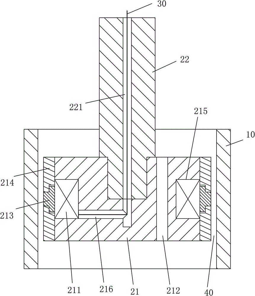
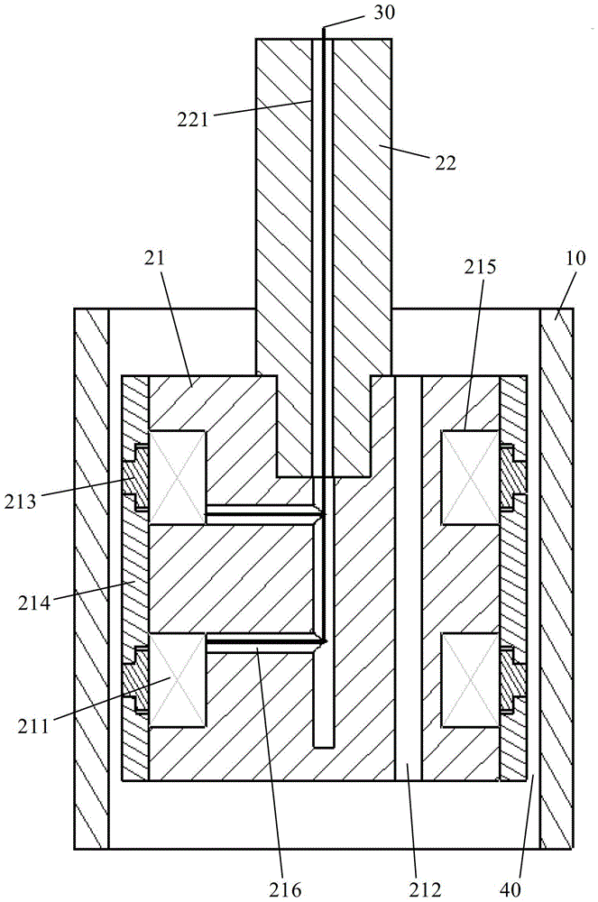
[0043] Such as Figure 2 to Figure 3 , the parallel normally through-hole magneto-rheological damper of the present invention includes a hollow cylinder 10, a piston is slidably arranged in the cylinder 10, and a piston rod 22 is fixedly connected to one end of the piston, and the piston rod 22 connects from one end of the cylinder 10 to protrude from the opening, for example, the piston rod 22 can be fixedly connected with the piston through screw connection or interference fit, and the piston slides in the cylinder body 10 driven by the piston rod 22, wherein: the piston includes a cylinder Shaped iron core 21, the side wall (outer circle side wall) of this iron core 21 is concavely provided with at least one ring-shaped wire slot 215, and each ring-shaped wire slot 215 is wound with an exciting coil 211, and the exciting coil 211 connects with the wire 30 The external corresponding power supply equipment (not shown in the figure) is connected, and the exterior of the excita...


PUM


Abstract

The invention discloses a method for calculating the zero-field and field-field damping force coefficients and damping force of a parallel normally through-hole magneto-rheological damper. The calculation method of the zero-field damping force coefficient of the magneto-rheological damper of the present invention is based on the first pressure difference coefficient C 1 , the second differential pressure coefficient C 2 Find that the field damping force coefficient of the magnetorheological damper of the present invention is based on the first differential pressure coefficient C 1 obtain, and the damping force calculation method of the present invention is based on the zero-field damping force coefficient and the field damping force coefficient calculation method of the magnetorheological damper of the present invention to determine the zero-field damping force coefficient and the field damping force coefficient. The whole obtaining process is simple, uncomplicated and fast, and the control of the damping force can be quickly realized.

Description

technical field [0001] The invention relates to a method for obtaining the zero-field damping coefficient, the field damping coefficient and the damping force of a magnetorheological damper with parallel normally through holes, and belongs to the technical field of semi-active control of structural magnetorheological vibration. Background technique [0002] Magnetorheological fluid is a kind of intelligent material sensitive to magnetic field. With the loading or withdrawal of external magnetic field, magnetorheological fluid converts between non-Newtonian fluid and Newtonian fluid. This conversion is reversible and continuous. The magnetorheological fluid has a large shear yield strength and fast response. The magnetorheological damper based on it is an ideal variable damping device and is widely used in structural vibration in vehicle engineering, weapon systems, civil engineering, aerospace and other fields. semi-active control. [0003] The existing magnetorheological d...

Claims


Application Information

Patent Timeline
Patent Type & Authority Patents(China)
IPC IPC(8): F16F9/53F16F9/32
Inventor 彭志召张进秋刘义乐毕占东刘峻岩贾进峰黄一斌张咏清张建岳杰张磊黄大山
Owner ACADEMY OF ARMORED FORCES ENG PLA
Why Eureka
Try Eureka