Design method of self-adaptive headlamp based on fly's-eye lens

A technology of fly-eye lens and design method, which is applied to lighting and heating equipment, headlights, lighting devices, etc., can solve the problems of long optical path of rectangular light guide tubes, waste of light energy, and difficulty in heat dissipation, etc., so as to improve the utilization of light energy Efficiency, reduce the difficulty of heat dissipation, good effect of light uniformity

Active Publication Date: 2014-10-15
江苏缤致光电科技有限公司
View PDF5 Cites 12 Cited by
  • Summary
  • Abstract
  • Description
  • Claims
  • Application Information

AI Technical Summary

Problems solved by technology

However, this solution has the following defects: (1) Both the low beam and the high beam are realized by digital micromirror elements, but the low beam requires a wider beam and a relatively uniform illuminance distribution, while the high beam requires concentrated light and a longer range
Therefore, when the parameters of the light source and the lens are unchanged, only using the micromirror on the digital micromirror element to realize the near beam and the far beam will cause defects such as low light utilization rate, difficult heat dissipation, and poor far and near beam effects.
(2) For low beam, high-speed, urban road and rainy and snowy weather lighting modes, it is necessary to form a light spot with a clear cut-off line on the light screen, and in this scheme, a 16:9 digital micromirror element is formed Or 4:3 rectangular spot, by calculation, only 51.88% or 53.6% of the micromirrors on the digital micromirror element are in the "ON" state (+12°), and nearly half of the micromirrors are in the "OFF" state ( -12°), which not only increases the workload of the digital micromirror element chip but also wastes a lot of light energy
(3) The rectangular light pipe has a long optical path and poor light uniformity effect, which will increase the volume of the system and reduce the accuracy of control

Method used


Image

  • Design method of self-adaptive headlamp based on fly's-eye lens
  • Design method of self-adaptive headlamp based on fly's-eye lens
  • Design method of self-adaptive headlamp based on fly's-eye lens

Examples


Embodiment Construction

[0025] Describe specific implementation below in conjunction with accompanying drawing and example.

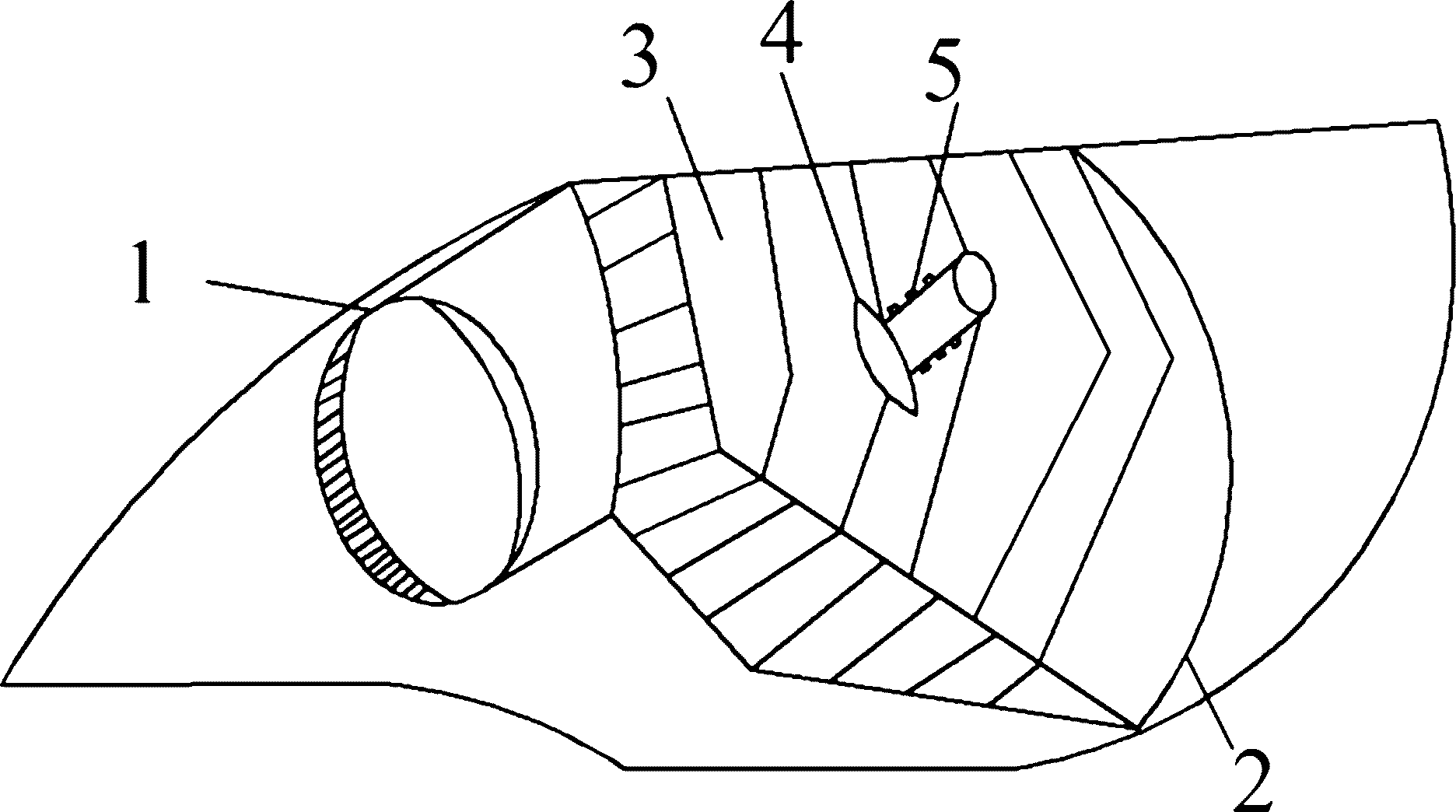
[0026] figure 1 is a schematic diagram of an adaptive headlight. It is composed of a projection part and a reflection part. When turning and going up and down slopes, a stepping motor is used to control the lights to deflect at a certain angle in the horizontal and vertical directions; the projection part contains a digital micromirror and a fly-eye lens for low beam and high-speed , urban roads and rainy and snowy weather lighting functions; the reflective part contains LED light sources and free-form reflectors to realize the high beam function. In the reflective part, the LED light source is evenly distributed on the cylindrical lamp holder, and there is a reflector at the front end of the cylindrical lamp holder, which can reflect the light directly emitted without passing through the reflector to the reflector.

[0027] figure 2 is a schematic diagram of the projected...


PUM


Abstract

The invention discloses a design method of a self-adaptive headlamp based on a fly's-eye lens. In the field of an automotive headlamp, an existing technology has the defects of insufficiently enough light control, low efficiency for solar energy utilization and the like. The self-adaptive headlamp comprises a projection part and a reflection part, wherein light rays emitted by an LED (Light Emitting Diode) are collimated by a paraboloid and a collimating lens, light beams are uniformly imaged on a digital micromirror by double rows of fly's-eye lenses and a convergent lens, and every row of fly's-eye lenses is composed of three small lenses of different shapes. The design method provided by the invention has the beneficial effects of being precise to control, many in realized lighting mode and good effect of various lighting mode; furthermore, long-distance light and short-distance light are separately realized, therefore the cooling difficulty can be reduced; in addition, uniform light spots with light and shade cut-off lines are formed in a digital micro-mirror by the fly's-eye lenses, therefore, light energy can be saved, and the efficiency for solar energy utilization can be improved; the double rows of fly's-eye lenses are served as a light equalization system, therefore short optical distance and good light equalization effect can be realized.

Description

technical field [0001] The invention relates to the technical field of an automobile headlight, in particular to a design method for an adaptive headlight based on a fly-eye lens. Background technique [0002] Adaptive Front Lighting System (AFS, Adaptive Front Lighting System) can timely and automatically adjust the light pattern of the headlight, the distance of the light beam and the intensity of the brightness according to the changes of the surrounding environment, providing a more suitable lighting range and lighting distance and lighting angle. The adaptive headlights are equipped with lighting modes such as high beam, low beam, curve, uphill and downhill, town road, high speed, rain and snow weather. The curve lighting mode provides enough illumination for curves by controlling the horizontal rotation angle of the headlights and eliminates the dark areas of the curves; the uphill and downhill lighting modes control the vertical deflection angle of the headlights to ...

Claims


Application Information

Patent Timeline
IPC IPC(8): F21S8/10F21V13/04F21V5/04F21W101/02F21W101/10F21Y101/02F21W107/10
CPCF21S41/675
Inventor 朱向冰王程郝文良田丽伟朱家俊张学峰陈瑾
Owner 江苏缤致光电科技有限公司
Why Eureka
Try Eureka