
High-amplitude picosecond balance pulse signal generator

A signal generator and balanced pulse technology, applied in the direction of electric pulse generator circuits, etc., can solve the problems that the voltage amplitude and pulse width cannot be taken into account at the same time, the pulse generation circuit structure is complex, etc. good effect

Active Publication Date: 2014-10-15
INST OF ELECTRONICS CHINESE ACAD OF SCI
View PDF3 Cites 14 Cited by
  • Summary
  • Abstract
  • Description
  • Claims
  • Application Information

AI Technical Summary

Problems solved by technology

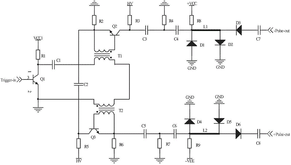
[0006] In view of the above technical problems, the present invention provides a picosecond balanced pulse signal generator with a large amplitude to overcome the complex structure of the existing pulse generating circuit and the dilemma that the voltage amplitude and pulse width cannot be taken into account at the same time

Method used


Image

  • High-amplitude picosecond balance pulse signal generator
  • High-amplitude picosecond balance pulse signal generator
  • High-amplitude picosecond balance pulse signal generator

Examples


Embodiment Construction

[0017] In order to make the object, technical solution and advantages of the present invention clearer, the present invention will be described in further detail below in conjunction with specific embodiments and with reference to the accompanying drawings. It should be noted that, in the drawings or descriptions of the specification, similar or identical parts all use the same figure numbers. Implementations not shown or described in the accompanying drawings are forms known to those of ordinary skill in the art. Additionally, while illustrations of parameters including particular values ​​may be provided herein, it should be understood that the parameters need not be exactly equal to the corresponding values, but rather may approximate the corresponding values ​​within acceptable error margins or design constraints. The directional terms mentioned in the embodiments, such as "upper", "lower", "front", "rear", "left", "right", etc., are only referring to the directions of the...


PUM


Abstract

The invention provides a picosecond balance pulse signal generator. The picosecond balance pulse signal generator comprises a pulse signal generation circuit, a first shaping circuit and a second shaping circuit. The pulse signal generation circuit comprises an avalanche triode pulse generation circuit which is formed by two cascaded avalanche triodes and used for generating a bipolar nanosecond balance pulse signal by an inputted negative polarity trigger pulse signal via triggering. The front end of the first shaping circuit is electrically connected with the pulse signal generation circuit and used for shaping the nanosecond balance pulse signal so that a picosecond pulse signal is generated. The front end of the second shaping circuit is electrically connected with the first shaping circuit and used for shaping trailing and overshoot of the picosecond pulse signal. The high-amplitude picosecond balance pulse signal generator is simple in structure and small and exquisite in circuit structure, and the generated balance pulse waveform is great in symmetry, small in trailing and high in amplitude so that the picosecond balance pulse signal generator can be applied to a pulse type ultra wide band radar system, and detection requirements of the pulse type radar system for different depth and resolution can be met.

Description

technical field [0001] The invention relates to the technical field of electronic components in the electronics industry, in particular to a large-amplitude picosecond balanced pulse signal generator. Background technique [0002] Ultra-wideband technology uses extremely narrow (nanosecond or picosecond) pulse signals as the transmission carrier, without signal modulation and demodulation, and directly obtains information by transmitting extremely narrow pulse signals. With the advantages of strong multipath fading capability, low power consumption, high bandwidth, and low power spectral density of transmitted signals, it is widely used in many fields such as wireless communication, wireless local area network, radar positioning, and tracking. The characteristics of the pulse signal itself basically determine that the ultra-wideband technology has the above advantages, so the selection and design of the pulse signal is very important for the ultra-wideband radar system. [...

Claims


Application Information

Patent Timeline
Patent Type & Authority Applications(China)
IPC IPC(8): H03K3/02
Inventor 夏新凡刘丽华管洪飞张群英方广有
Owner INST OF ELECTRONICS CHINESE ACAD OF SCI
Learn More