
Injection flow protection device and method for die casting pouring

A technology of mold casting pouring and protection device, which is applied in the field of mold casting pouring, which can solve problems such as rapid temperature drop of molten steel, easy formation of nodules, pinholes or slag volume problems, etc., so as to reduce material consumption costs, and is not easy to deform or fall off , Reduce the effect of inclusion defects

Active Publication Date: 2014-10-22
宝武特种冶金有限公司
View PDF5 Cites 14 Cited by
  • Summary
  • Abstract
  • Description
  • Claims
  • Application Information

AI Technical Summary

Problems solved by technology

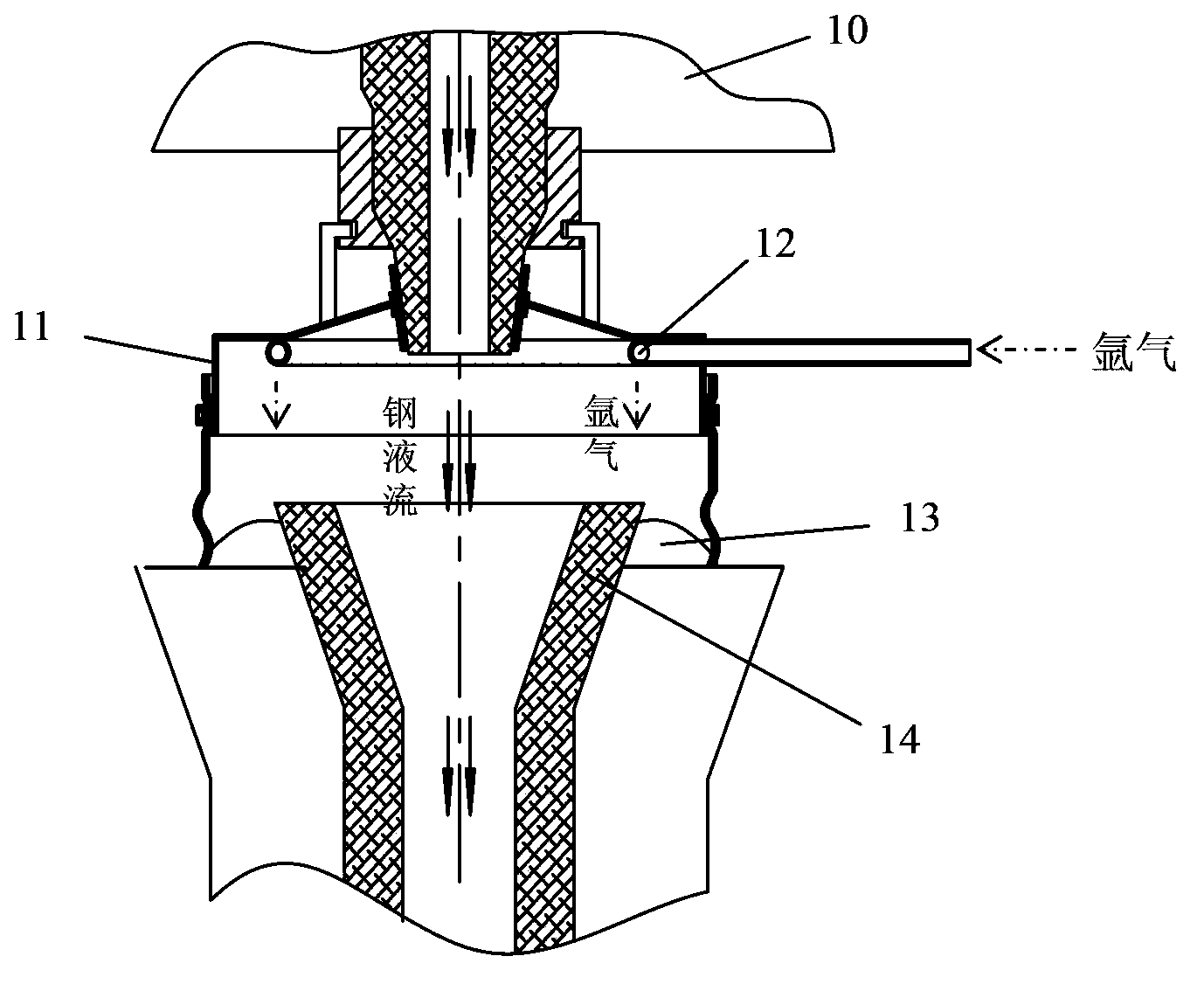
[0005] 1. During the pouring process, since the argon gas injection direction is the same as the pouring direction of the molten steel flow, a tubular protective gas mist wall with argon ring as the busbar and a certain height will be formed along the direction of the argon ring vent hole, similar to Although a cylinder can effectively prevent the entry of external oxidizing gas, it cannot effectively remove the oxidizing atmosphere remaining in the gas mist wall in the early stage, so there is still the possibility of secondary oxidation of molten steel at the initial stage of pouring;
[0006] 2. There is only one argon ring in the protective cover, and when the outer dimension of the protective cover is fixed, the argon flow rate in one argon ring is relatively low, and the argon cannot fill the entire protective cover in a short time. Cover, especially the area between the argon ring and the ladle nozzle, the argon can only gradually fill this area in the later stage, so the argon protection pouring effect lags behind seriously, and it usually takes 2-3 minutes to highlight the effect, especially for pouring early stage;
During the pouring process, argon gas is ejected from the vent hole. Since the entire protective cover is in a completely sealed state, there is no vent hole to discharge the compressed gas in the protective cover. Therefore, in the later stage of pouring, as the argon gas is continuously filled In the gas shield, the amount of argon in the shield is increasing and the pressure is increasing. Excessive argon is easily involved in the gating system with the molten steel flow, forming subcutaneous air bubbles and needles during the solidification of the ingot. Hole or slag quality problems;
[0008] 4. The flow rate of argon is required to be controlled at 20-30Nm 3 / h, after the flow rate of argon gas is quite large, and because the diameter of the vent hole is 5-6mm, it is easier to produce argon flow rate with a larger injection distance. Under the control of the flow rate, a strong jet will be generated directly, and the argon flow will directly impact on the periphery of the gate 14 of the intermediate injection tube. Since the gap between the gate of the intermediate injection tube and the iron shell of the intermediate injection tube is filled with quartz sand 13, the quartz The upper surface of the sand is only 3-5cm lower than the upper surface of the center injection tube gate. When the argon flow rate is too large, a strong argon injection pressure will be generated (take the argon flow rate as 20Nm 3 / h, the diameter of the pores on the argon ring is 5-6mm, a total of 30 small holes, assuming that all the pores are intact and not blocked, the average flow rate of a single hole is 0.67Nm 3 / h, the injection flow per second of a single hole is 185ml / s, the flow rate is relatively high), the quartz sand around the gate is easily drawn into the gate by the strong convective argon, and then various non-metallic inclusions are produced, affecting the steel ingot quality;
[0009] 5. After the argon gas flow rate is too large, the argon gas will form a circuit between the vent hole and the molten steel flow during the pouring process, and the argon gas will directly contact the pure molten steel flow during the injection process, and will be damaged by the argon gas. The large temperature difference between the temperature and the molten steel flow causes the argon gas to absorb a large amount of heat from the exposed steel flow, which in turn causes the temperature of the molten steel to drop too quickly, especially in the vicinity of the ladle nozzle, which is easy to form nodules, which seriously affects the on-site production and the steel ingot product quality;

Method used


Image

  • Injection flow protection device and method for die casting pouring
  • Injection flow protection device and method for die casting pouring
  • Injection flow protection device and method for die casting pouring

Examples


Embodiment Construction

[0054] The specific implementation manners of the present invention will be described in detail below in conjunction with the accompanying drawings of the embodiments.

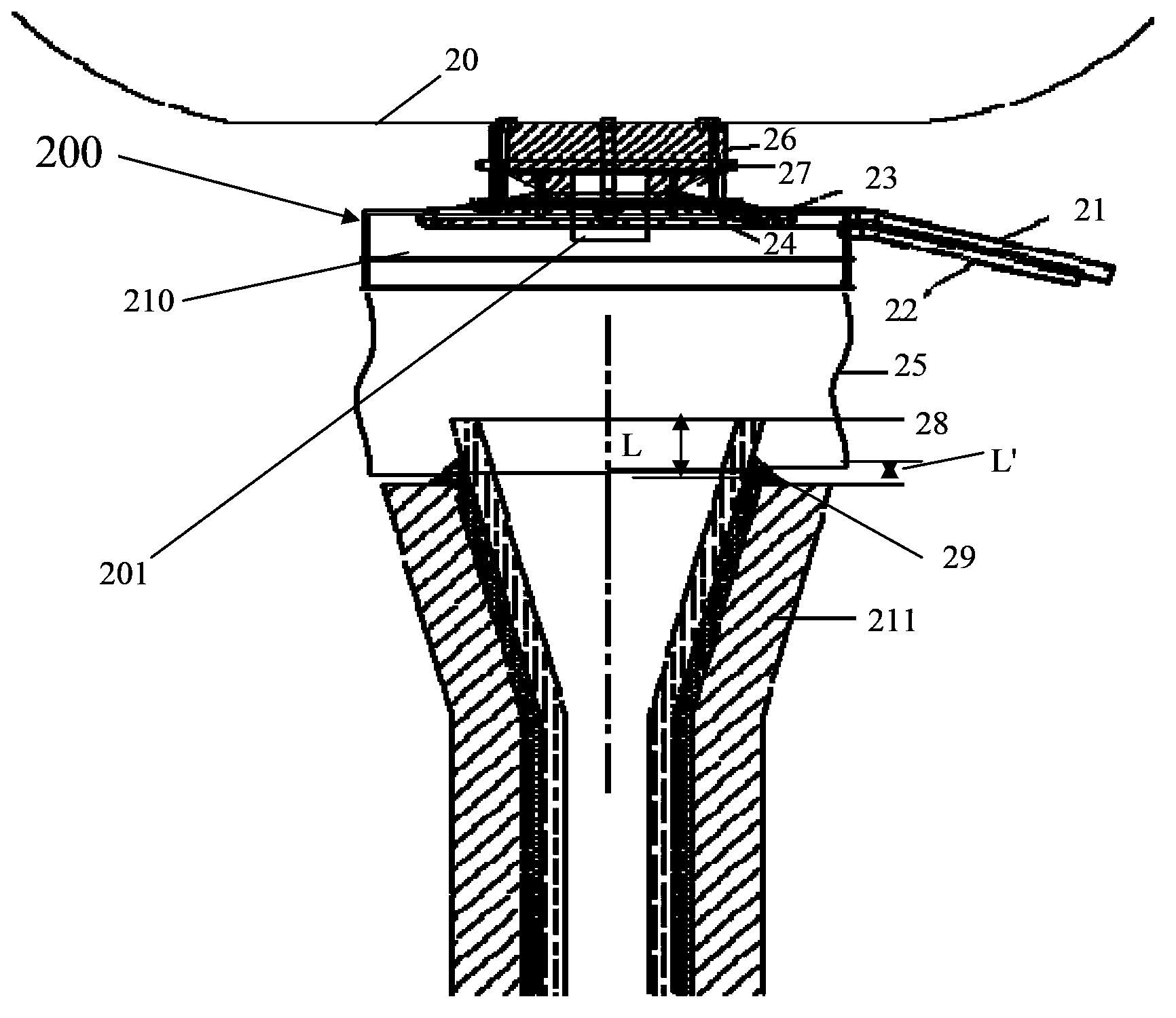
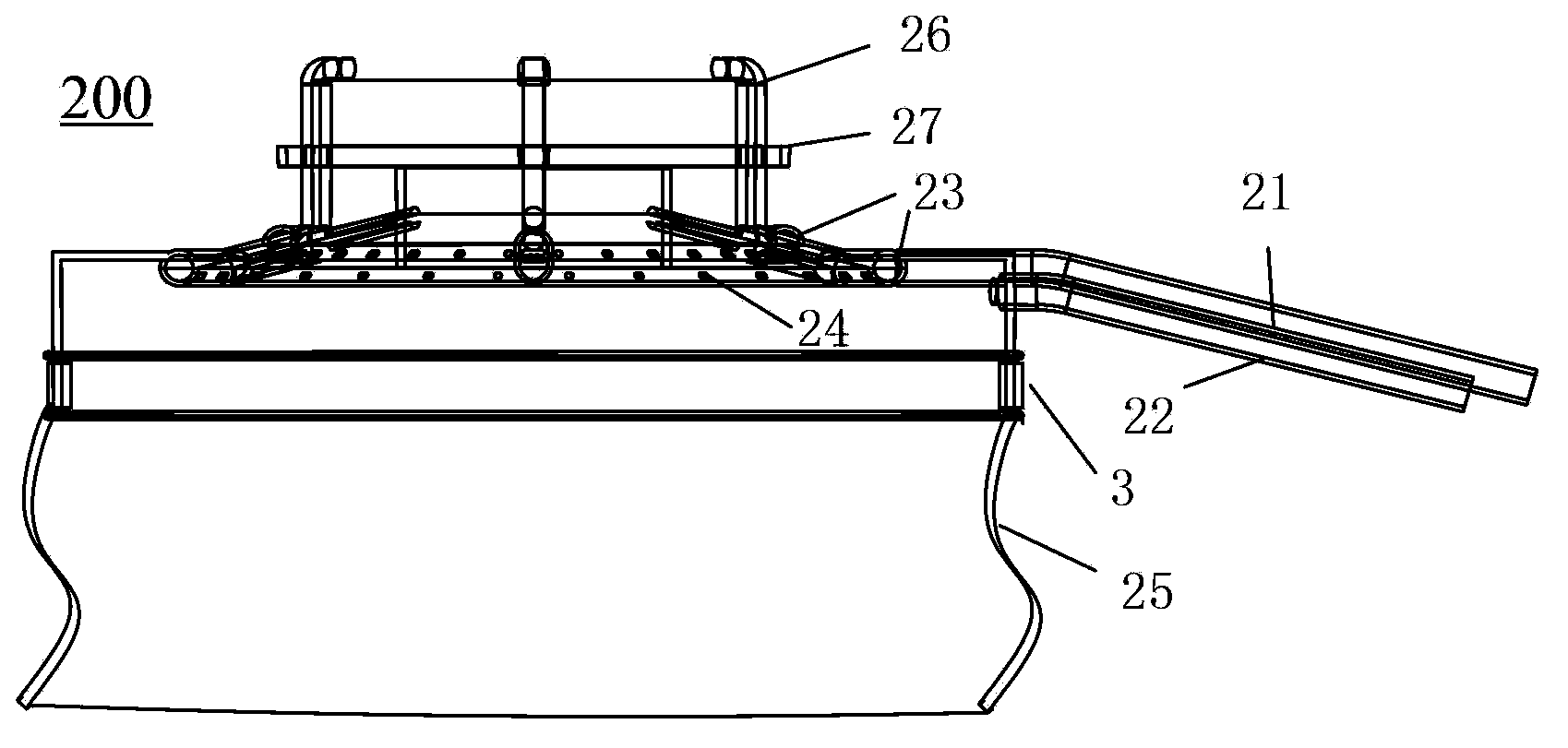
[0055] see Figure 2-Figure 4 , the structure of the pouring flow protection device for mold casting pouring of the present invention is as follows:

[0056] A protective cover 200 is installed between the bottom of the ladle 20 for die casting pouring and the middle pouring pipe gate 28 of the die casting pouring equipment, filled with argon to isolate the molten steel flow from contacting the outside air during the die casting pouring process. In order to prevent the secondary oxidation of molten steel, the protective cover 200 includes:

[0057] The outer cover 210 is an inverted T-shaped round cover made up of two round covers with a small top and a large bottom, and the two ends are not closed;

[0058] An argon blowing tube 21, one end leads into the outer cover 210 and is fixed to the wall of the larg...


PUM


Abstract

The invention discloses an injection flow protection device and method for die casting pouring, relates to die casting pouring technology and solves the problem of secondary oxidation of molten steel. A protection cover is mounted between the bottom of a steel ladle for die casting pouring and a middle injection pipe sprue of die casting pouring equipment and comprises an outer cover, an argon blowing pipe, a sampling pipe, two argon rings, an argon protection overskirt and three supporting feet, each argon ring is composed of a big ring pipe and a small ring pipe which are disposed in the outer cover and communicated, and multiple argon feeding holes formed in the ring pipes horizontally face the center of a circular ring; a gap is reserved between the bottom of the argon protection overskirt and the middle injection pipe sprue, the supporting feet are connected with the protection cover and are detachable connecting parts of the protection cover and the steel ladle, the tops of the supporting feet are disposed in a T-shaped round clamping groove of an outer ring of a water port at the bottom of the steel ladle in a clamped manner, and vertical distance between the middle injection pipe sprue of the die casting pouring equipment and a hollow injection pipe iron shell. By the injection flow protection device and method, argon flow can be controlled effectively during die casting pouring work, and secondary oxidation of the molten steel is avoided while pouring is unaffected.

Description

technical field [0001] The invention relates to die-casting pouring technology, in particular to a flow protection device and method for die-casting pouring. Background technique [0002] In the metallurgical production process, the commonly used technological process is: electric furnace-refining-casting, and the pouring process is a particularly important link. Molten steel pouring is divided into die casting and continuous casting. With the development of the steel industry, die casting is gradually replaced by continuous casting. Instead of the die casting process, the die casting process is still an indispensable process in iron and steel metallurgical production. [0003] The control of mold casting pouring quality plays a particularly important role in the quality of finished products. In the pouring process, the key link related to the quality of steel ingots is mainly to prevent secondary oxidation of molten steel. In die casting production, pouring is usually ado...

Claims


Application Information

Patent Timeline
IPC IPC(8): B22D7/12
Inventor 周同军顾家强罗辉奚平璐
Owner 宝武特种冶金有限公司
Learn More