
Motor rotor processing machine and motor rotor adding method

A technology of motor rotor and processing machine, which is applied in the direction of manufacturing stator/rotor body, etc., to reduce the effect of surface damage

Active Publication Date: 2017-07-07
JIANGSU HENGTE GRP VALTTE ELECTRIC
View PDF5 Cites 0 Cited by
  • Summary
  • Abstract
  • Description
  • Claims
  • Application Information

AI Technical Summary

Problems solved by technology

[0005] The invention provides a motor rotor processing machine and a motor rotor processing machine, which overcome the shortcomings of manual removal of rotor tailings and lay a foundation for the butt joint production of rotor casting and post-processing

Method used


Image

  • Motor rotor processing machine and motor rotor adding method
  • Motor rotor processing machine and motor rotor adding method
  • Motor rotor processing machine and motor rotor adding method

Examples


Embodiment 1

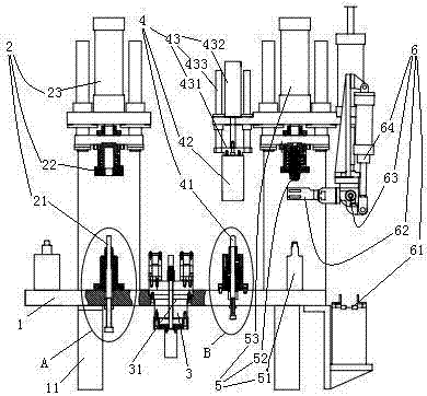
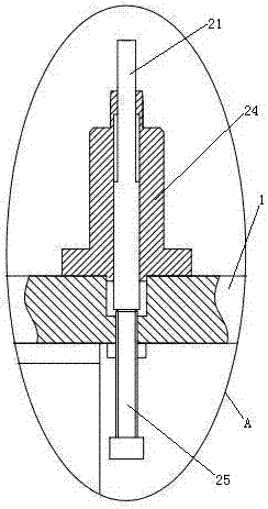
[0036] Embodiment one, see figure 1 , a motor rotor tailing removal machine, comprising a frame 1 and a tailings rotor disconnection mechanism 2, a tailings removal mechanism 3, a core removal mechanism 4, and a rotor end ring arranged in sequence on the frame 1 Hole chamfering mechanism 5 and blanking mechanism 6. Between the tailing rotor disconnection mechanism 2 and the tailing removal mechanism 3, between the tailing removal mechanism 3 and the core removal mechanism 4, and between the core removal mechanism 4 and the inner hole chamfering mechanism of the rotor end ring 5 There are rotor transfer manipulators between them. The rotor transfer manipulator is not shown in the figure, it is the manipulator used for the existing transfer workpiece.

[0037] The frame 1 is provided with liftable support feet 11 . The supporting feet 11 are cylinders.

[0038] The tailings rotor breaking mechanism 2 includes a support rod 21 , a pressing sleeve 22 and a press 23 located abo...

Embodiment 2

[0065] Embodiment two, the difference with embodiment one is:

[0066] see Figure 9 , also includes refueling device 9. The refueling device 9 includes an oil storage tank 91 , an oil outlet channel 92 , a membrane rupture rod 93 , a corrosive liquid storage tank 94 , a periodic rotting buoy 95 and a guide rod 96 .

[0067] The oil storage tank 91 is connected together with the regularly putrefying formula buoy 95 by a connecting rod 98 . The connecting rod 98 and the regular rotting buoy 95 are detachably connected together by bolts. The oil storage tank 91 includes at least two cavities 911 which in this embodiment are four cavities 911 which are sequentially sleeved and fixed together. Lubricating oil is housed in the cavity 911 (not shown in the lubricating oil figure). The lower wall of the cavity 911 is provided with an oil outlet 912 . The oil outlet 912 is sealed and connected with a sealing membrane 913 . A total of 4 oil outlets 912 of the 4 cavities are locate...


PUM


Abstract

The present invention relates to electric machines. A motor rotor processing machine, comprising a frame with liftable support feet, a tailing rotor disconnection mechanism, a tailing removal mechanism and a core removal mechanism, a tailing rotor disconnection mechanism and a tailing removal mechanism There is a rotor transfer manipulator between the tailing material removal mechanism and the core removal mechanism. The tailing material rotor disconnection mechanism includes a support rod, a pressure sleeve, and a pressure that drives the pressure sleeve and the support rod for separation and closing. machine, the tailing material removal mechanism includes a rotor fixing mechanism, a tailing material clip, a swing mechanism that drives the tailing material clip to swing, and a first moving mechanism that drives the tailing material clip to move away; the core removal mechanism includes a mandrel, a core fixing mechanism And the briquetting block, and the second moving mechanism that drives the briquetting block closer to the push rod and the third moving mechanism that drives the core fixing mechanism to move away. The invention provides a motor rotor processing machine and a motor rotor adding method, which overcome the disadvantages of manual removal of rotor tailings.

Description

technical field [0001] The invention relates to a motor, in particular to a motor rotor processing machine and a motor rotor adder. Background technique [0002] The rotor is the rotating part of the motor. It is composed of rotor core, rotor winding and rotating shaft. Its function is to obtain the rotational torque under the action of the rotating magnetic field. The rotor is divided into a squirrel cage rotor and a wound rotor according to its structure. The squirrel-cage rotor consists of a rotor squirrel cage and a rotor core. The rotor core is composed of a number of ring-shaped iron sheets with openings on the inner peripheral surface which are laminated and riveted together, and the openings on the iron sheets are butted to form grooves for guide bars of the rotor core. There are two main forms of the rotor squirrel cage: one is formed by installing copper bars in the guide bar groove of the rotor core, and the two ends are welded with rotor end rings; the other is...

Claims


Application Information

Patent Timeline
Patent Type & Authority Patents(China)
IPC IPC(8): B22D29/00B22D31/00H02K15/02
Inventor 危金兰
Owner JIANGSU HENGTE GRP VALTTE ELECTRIC
Learn More