In-vehicle Engine Control Device And Control Method Thereof
一种控制装置、控制方法的技术,应用在发动机控制、机器/发动机、电气控制等方向,能够解决未升压用感应元件驱动电流检测等问题,达到抑制功耗、降低温度上升、准确设定的效果
- Summary
- Abstract
- Description
- Claims
- Application Information
AI Technical Summary
Problems solved by technology
Method used
Image

Examples
Embodiment approach 1
[0033] (1) Detailed description of the structure
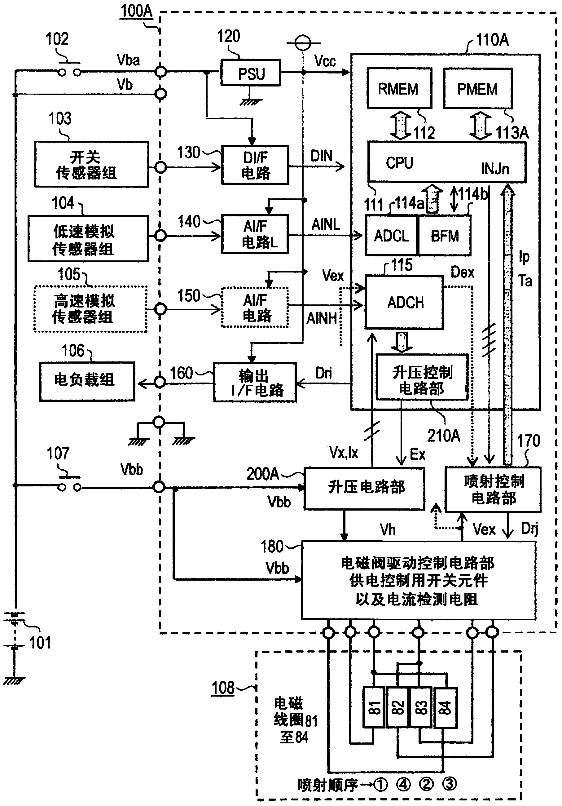
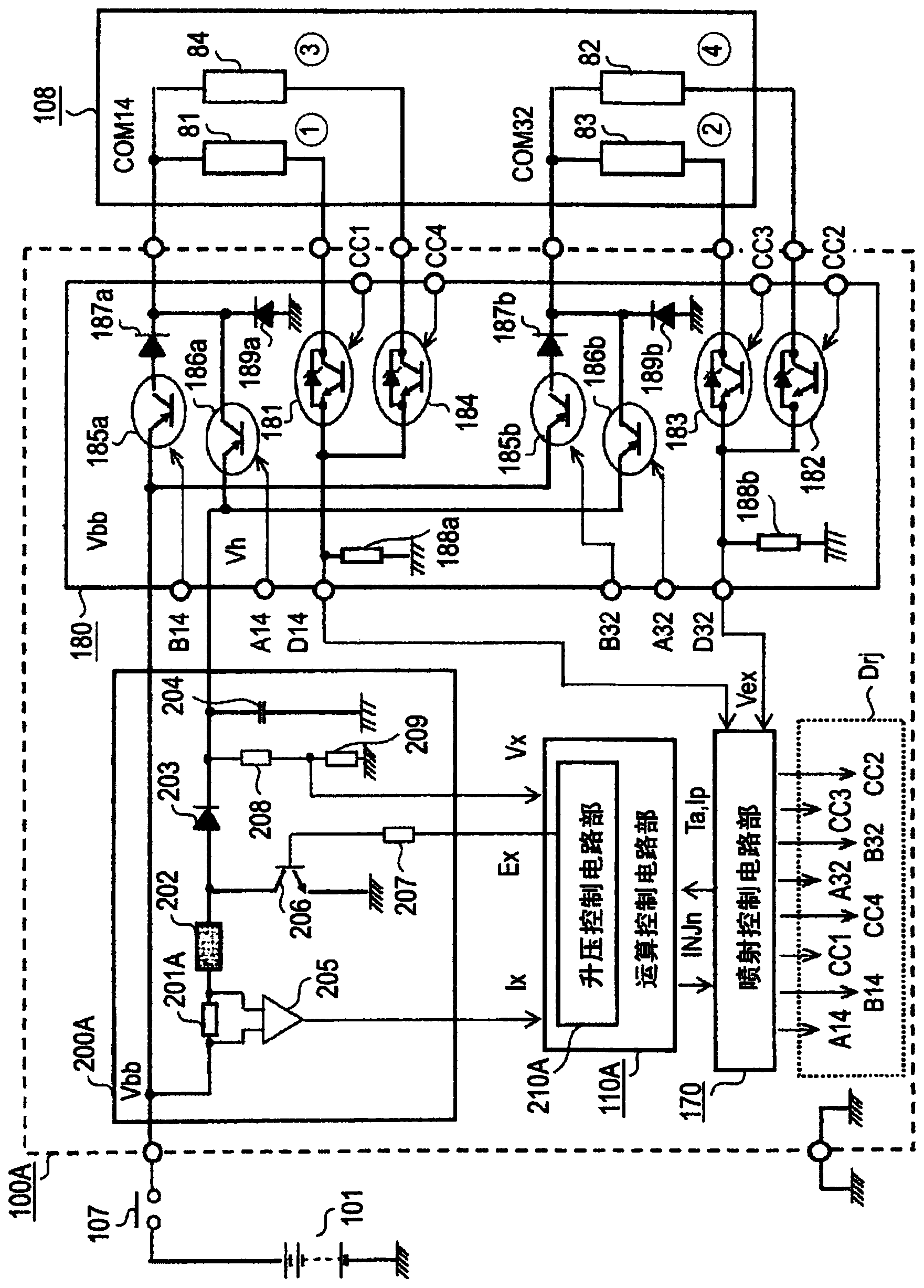
[0034] In the following, the general circuit block diagram of the device according to Embodiment 1 of the present invention will be described. figure 1 Be explained. figure 1 Among them, the in-vehicle engine control device 100A is composed of an arithmetic control circuit unit 110A configured as a single-chip or two-chip integrated circuit element together with a boost control circuit unit 210A or an injection control circuit unit 170 described later. In 108 , a solenoid valve drive control circuit unit 180 for the solenoid coils 81 to 84 described later and a booster circuit unit 200A serving as a high-voltage power supply for rapidly exciting the solenoid coils 81 to 84 are mainly configured. First, the on-vehicle battery 101 connected to the outside of the on-vehicle engine control device 100A directly supplies the on-vehicle engine control device 100A with the battery voltage Vb, and supplies the on-vehicle engine contro...
Embodiment approach 2
[0090] (1) Detailed description of the structure
[0091] Below, with and figure 1 Centering on the different points of the device, the overall circuit block diagram of the device according to Embodiment 2 of the present invention is Figure 7 Be explained. The main difference between the vehicle-mounted engine control device 100B in the second embodiment and the vehicle-mounted engine control device 100A in the first embodiment is that Figure 8 , Figure 9 The difference between the boost control circuit unit 210B described later and the boost control circuit unit 210A, and other overall configurations, figure 1 and Figure 7 exactly the same. As a result, the calculation control circuit unit 110A and the program memory 113A are replaced with the calculation control circuit unit 110B and the program memory 113B, and the same reference numerals in each figure indicate the same or corresponding parts.
[0092] next, yes Figure 7 The detailed block diagram of the part c...
Embodiment approach 1
[0115] Points and Features of Embodiment 1 and Embodiment 2
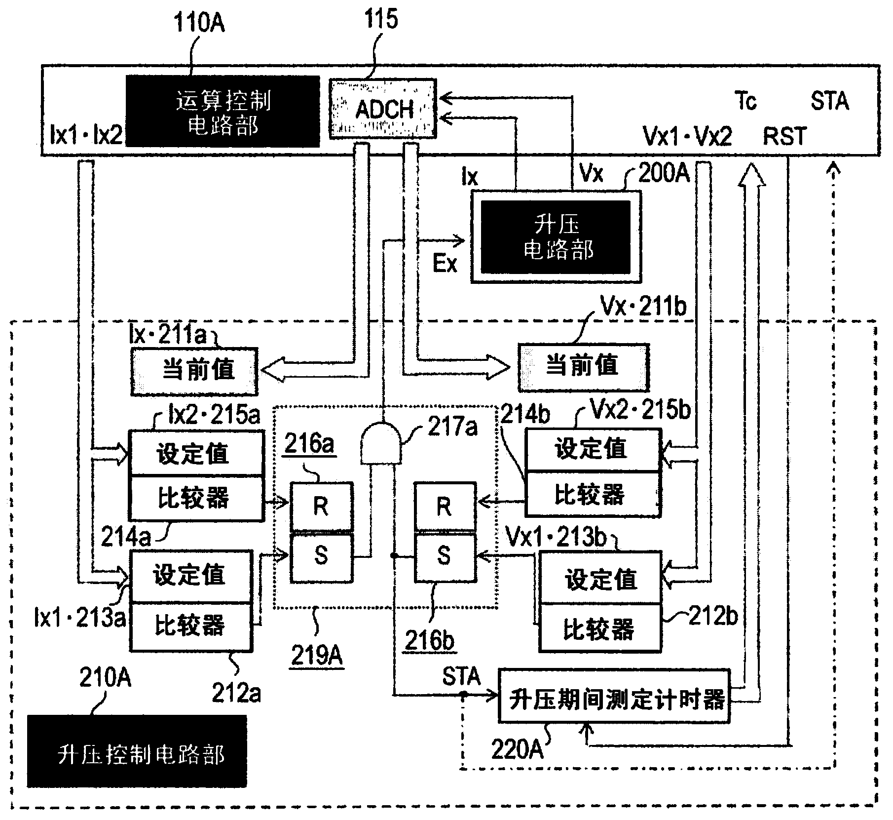
[0116] As is clear from the above description, in the vehicle-mounted engine control method used in the vehicle-mounted engine control device according to Embodiment 1 or Embodiment 2 of the present invention, the boost control circuit units 210A and 210B further include a boost period measuring timer. The meter 220A or the standby time measurement timer 220B, the boost period measurement timer 220A measures the charging time Tc, the charging time Tc is the charging voltage of the above-mentioned high-voltage capacitor 204 from the above-mentioned valve opening command signal INJn (n= 81-84) from generation to the time until the minimum voltage Vx0 is reduced to the minimum voltage Vx0 due to rapid excitation of the above-mentioned electromagnetic coils 81-84, and then reaches the above-mentioned target upper voltage Vx2 by recharging, the standby time measurement timer 220B measures Charging remaining time Tb, the ...
PUM
 Abstract
Description
Claims
Application Information
 - R&D
- Intellectual Property
- Life Sciences
- Materials
- Tech Scout
- Unparalleled Data Quality
- Higher Quality Content
- 60% Fewer Hallucinations
Browse by: Latest US Patents, China's latest patents, Technical Efficacy Thesaurus, Application Domain, Technology Topic, Popular Technical Reports.
© 2025 PatSnap. All rights reserved.Legal|Privacy policy|Modern Slavery Act Transparency Statement|Sitemap|About US| Contact US: help@patsnap.com