Low-thermal-resistance radiating LED lamp

An LED lamp and LED lamp bead technology, applied in the field of lighting, can solve the problems of small micro contact area, less thermal conductivity than aluminum radiator, affecting heat dissipation effect, etc., to reduce process time and labor needs, ensure life and brightness, and heat dissipation. obvious effect

Inactive Publication Date: 2014-10-22
CHONGQING SANGNAIMEI PHOTOELECTRIC TECH
View PDF0 Cites 2 Cited by
  • Summary
  • Abstract
  • Description
  • Claims
  • Application Information

AI Technical Summary

Problems solved by technology

At present, when using ceramic substrates, although the thermal conductivity of ceramic substrates is high, since the heat transfer between ceramic substrates and radiators is through mechanical contact heat transfer, the microscopic contact area is much smaller than the actual surface area, especially for heat dissipation. When the surface of the device is rough or there are burrs and foreign objects on the surface, the microscopic contact area is smaller, which seriously affects the heat dissipation effect
[0005] At present, in order to improve this problem, we will apply a thin layer of thermal conductive silicone grease between the circuit board and the heat sink to fill the tiny gaps in between. The requirement is to apply it thinly and evenly, but this is not an easy task. The thing, because the thermal grease does not have good fluidity
If the thermal conductive silicone grease is not applied thinly or evenly enough, the heat transfer effect will still be poor, and the life and brightness of the entire LED lamp will still be reduced. In addition, the thermal conductivity of the thermal conductive silicone grease itself is not high, generally 2w / m·k About, the highest is only 5w / m·k, far less than the thermal conductivity of aluminum radiator or ceramic substrate

Method used


Image

  • Low-thermal-resistance radiating LED lamp

Examples


Embodiment Construction

[0017] The present invention will be further described below through specific examples, but not in order to limit the present invention, all within the spirit and principle of the present invention, any modification, equivalent replacement, improvement etc. all should be included within the scope of protection of the present invention .

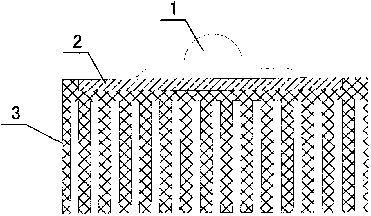
[0018] Such as figure 1 As shown, the low thermal resistance heat dissipation LED lamp includes a plastic heat sink 3 , LED lamp beads 1 and a ceramic substrate 2 , the LED lamp beads 1 are soldered on the upper surface of the ceramic substrate 2 , and the ceramic substrate 2 is embedded on the top of the plastic heat sink 3 .

[0019] In this embodiment, the upper surface of the ceramic substrate 2 and the upper surface of the plastic heat sink 3 are on the same plane; the plastic heat sink 3 is made of thermally conductive plastic.

[0020] In actual application, the upper surface of the ceramic substrate 2 can also be higher than the uppe...


PUM


Abstract

The invention relates to a low-thermal-resistance radiating LED lamp and belongs to the field of lighting techniques. The low-thermal-resistance radiating LED lamp comprises a plastic radiator, an LED and a ceramic substrate. The low-thermal-resistance radiating LED lamp is characterized in that the LED is arranged on the upper surface of the ceramic substrate by soldering, and the ceramic substrate is embedded in the top of the plastic radiator. The low-thermal-resistance radiating LED lamp is simple in structure and has significant radiating effect, the service life and brightness of the high-power LED lamp are effectively ensured, less heat-conducting silicone is applied, a step of mounting an LED lamp panel on a radiator is omitted, and accordingly, process time is shortened, demanded labor is reduced, and production cost is reduced.

Description

technical field [0001] The invention relates to a low thermal resistance heat dissipation LED lamp, which belongs to the technical field of lighting. Background technique [0002] At present, the existing LED lamps generally mount the LED lamp beads on the circuit board through chip technology (such as soldering tin), and then fix the circuit board on the radiator, and coat the thermal conductive silicone grease between the circuit board and the radiator. The heat emitted by the LED lamp beads is transferred to the solder, the circuit board and the heat sink in turn through its own heat dissipation pad, and finally the heat sink dissipates the heat into the air through the surface. [0003] Nowadays, high-power LEDs used for lighting are generally made into SMD components with heat dissipation pads to facilitate heat transfer and improve heat dissipation performance. The circuit boards commonly used in LED lighting generally use aluminum substrates. Since aluminum is conduc...

Claims


Application Information

Patent Timeline
Patent Type & Authority Applications(China)
IPC IPC(8): F21S2/00F21V29/00F21Y101/02
Inventor 吴海龙
Owner CHONGQING SANGNAIMEI PHOTOELECTRIC TECH
Why Eureka
Try Eureka