Mirror object measuring device and method based on binocular vision

A technology of binocular vision and measuring device, which is applied in the field of contour three-dimensional reconstruction, can solve the problems that the image acquisition system is difficult to capture reflected light, relies on normal information, and is difficult to achieve, and achieves the effects of simple system structure, high measurement accuracy and convenient use.

Inactive Publication Date: 2014-10-22
SHENYANG INST OF AUTOMATION - CHINESE ACAD OF SCI
View PDF7 Cites 44 Cited by
  • Summary
  • Abstract
  • Description
  • Claims
  • Application Information

AI Technical Summary

Problems solved by technology

How to judge whether an image feature corresponds to a real scene point or a specular reflection of another scene point? This ambiguity poses a serious problem for vision techniques based on feature detection and matching
Secondly, during specular reflection, the reflection direction of the light beam depends on the incident direction and the normal direction of the object surface, which makes it difficult for the image acquisition system to capture the reflected light. Even if the reflected light is captured, the surface shape data of the measured mirror object depends heavily on the object face normal information
As for the measurement of transparent objects, due to the double influence of specular reflection and internal refraction, it becomes particularly difficult

Method used


Image

  • Mirror object measuring device and method based on binocular vision
  • Mirror object measuring device and method based on binocular vision
  • Mirror object measuring device and method based on binocular vision

Examples


Embodiment Construction

[0039] A preferred example of the present invention is described in detail as follows in conjunction with accompanying drawing:

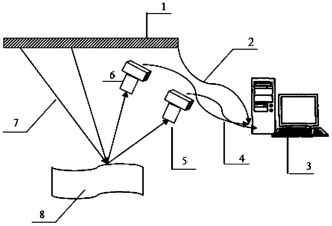
[0040] Such as figure 1 As shown, a mirror object measuring device based on binocular vision is composed of an LCD liquid crystal display 1, two industrial cameras, and a computer 3; the LCD liquid crystal display 1 is horizontally installed on the frame of the measuring device of the present invention and placed at 200mm above the measured mirror object, connected to the computer 3 through a cable, controlled by the computer 3 to generate sinusoidal fringe patterns, and project these fringe patterns on the surface of the object 8 to be measured; the industrial camera An 8mm fixed-focus lens is used, installed on one side of the LCD liquid crystal display at an angle of 65 degrees to the horizontal direction, and is symmetrical to the measured object 8, so that the distance between the lens and the surface of the measured object is 300mm, and the bi...


PUM


Abstract

The invention relates to a mirror object measuring device and a method based on binocular vision. According to the device, a computer is connected with a liquid crystal display device and a camera, and the liquid crystal display device is arranged above a measured mirror object. The measuring method comprises steps that: a binocular camera is calibrated, an internal matrix of the binocular camera and a rotating translation matrix between the cameras are acquired, and relative position relations between the liquid crystal display device and the binocular camera are acquired; a sine fringe is generated by the computer, the liquid crystal display device is controlled to project an image of the sine fringe to the measured mirror object, and a virtual image which is formed on a surface of the measured mirror object and is generated by the sine fringe shot by the camera is inputted to the computer; information of the virtual image acquired by the camera is processed by the camera according to the calibrated relative position relations and the internal matrix of the camera to acquire a three-dimensional profile of the surface of the measured mirror object. The mirror object measuring device has a simple structure, can realize non-contact measurement, needs no contact probes in the traditional technology, reduces measurement cost and improves measurement efficiency.

Description

technical field [0001] The invention relates to a contour three-dimensional reconstruction technology, in particular to a device and method for measuring the three-dimensional contour of a specular object surface using a binocular camera. Background technique [0002] With the increase of measurement requirements and the development of photoelectric technology, vision-based non-contact measurement technology has been developed rapidly. The 3D shape visual measurement of objects has a wide range of applications in many fields such as reverse engineering, robot vision, quality inspection, digital medical treatment, cultural relic protection, film and television advertising, and clothing manufacturing. The three-dimensional profile measurement technology of mirror object surface has important application value. In engineering, there are a large number of specular surfaces that need to be measured. For example, in the fields of machinery manufacturing, cultural relics protecti...

Claims


Application Information

Patent Timeline
Patent Type & Authority Applications(China)
IPC IPC(8): G01B11/25
Inventor 王国强赵吉宾夏仁波李论付生鹏杨林
Owner SHENYANG INST OF AUTOMATION - CHINESE ACAD OF SCI
Why Eureka
Try Eureka