

Drawing force detector and test method thereof
Patent Information
- Authority / Receiving Office
- CN · China
- Patent Type
- Applications(China)
- Current Assignee / Owner
- SHENZHEN POLYTECHNIC
- Publication Date
- 2014-10-22
- Estimated Expiration
- Not applicable · inactive patent
Smart Images
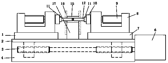
Figure 1 
Figure 2 
Figure 3
Abstract
Description
technical field
[0001] The invention relates to the technical field of precision parts detection, and specifically discloses a precision casing bidirectional pullout force detector and a testing method thereof. Background technique
[0002] The precision sleeve involved in the present invention belongs to the optical fiber connector. The optical fiber connector is a device for detachable (movable) connection between the optical fiber and the optical fiber. The energy can be coupled into the receiving optical fiber to the greatest extent, and the impact on the system caused by its intervention in the optical link is minimized. There are many types of fiber optic connectors, which can be divided into FC, SC, ST, MU, LC, etc. according to the connection method; according to the casing material, they can be divided into zirconia ceramic materials, SUS materials, glass materials, plastic materials, metal materials, etc.
[0003] With the breakthrough and maturity of the most cut...