Water quality sensor

A water quality sensor and medium technology, applied in the field of water quality sensors, can solve the problems of complex sensor design, large power consumption of motors, and large volume, and achieve the effects of resisting biological pollution for a long time, increasing continuous use time, and increasing irradiation intensity

Inactive Publication Date: 2014-10-22
SUZHOU YULING ENVIRONMENTAL PROTECTION TECHCO
View PDF9 Cites 4 Cited by
  • Summary
  • Abstract
  • Description
  • Claims
  • Application Information

AI Technical Summary

Problems solved by technology

Since the water quality sensor needs to be deployed in the water environment for a long time, it is inevitable that a large amount of biological pollution such as animals and plants may accumulate on the sensor, thereby affecting the accuracy of the sensor
[0003] In the existing design, a variety of methods to prevent the accumulation of biological contamination on the sensor have been developed: the more common one is to assemble a brush or sponge pad driven by a motor on the sensor, and clean the surface of the sensor through mechanical action , but its disadvantage is that the volume is large, and the motor consumes a lot of power, and, more fatally, since this type of water qu

Method used


Image

  • Water quality sensor
  • Water quality sensor
  • Water quality sensor

Examples


Embodiment 1

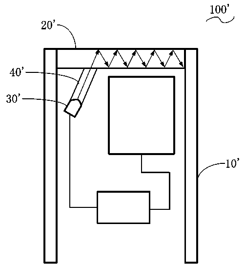
[0029] ginseng figure 2 The water quality sensor 100' includes a housing 10' and an optical window 20' installed on the housing 10', the water quality sensor 100' also includes an ultraviolet light emitting source 30', and a light guide tube 40 connected to the optical window 20' ', the ultraviolet light emitted from the ultraviolet light emitting source 30' passes through the light guide 40' incident optical window 20', and the ultraviolet light emitting source 30' is set so that the ultraviolet light emitted by it is incident on the optical window 20' The incident angle is greater than arcsin(n1 / n2); wherein, n1 is the refractive index of the water body where the water quality sensor 100' is configured, and n2 is the refractive index of the optical window 20'.

[0030] Here, it is preferable to set the connection between the light pipe 40' and the optical window 20' as a tight fit by default, so as to ensure that the ultraviolet light will not be refracted by the air when i...

Embodiment 2

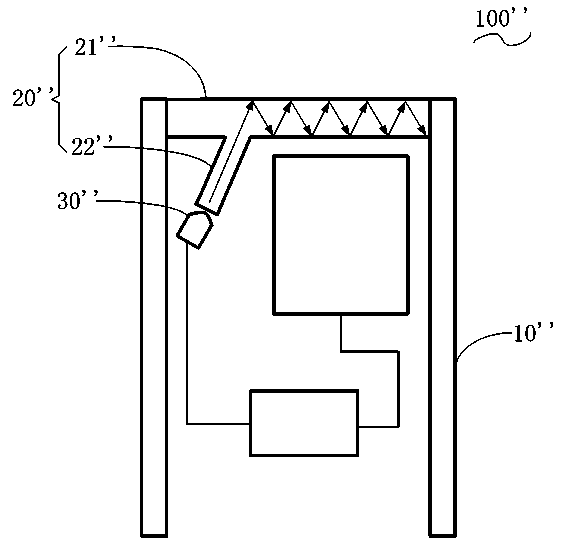
[0035] ginseng image 3 The water quality sensor 100'' includes a housing 10'' and an optical window 20'' installed on the housing 10'', the optical window 20'' includes a window part 21'' and a light guide connected to the window part 21'' part 22'', the water quality sensor 100'' also includes an ultraviolet light emitting source 30'', the ultraviolet light emitted from the ultraviolet light emitting source 30'' enters the window part 21'' through the light guide part 22'', and the ultraviolet light The light emitting source 30'' is set so that the incident angle of the emitted ultraviolet light incident on the window part 21'' is greater than arcsin (n1 / n2); wherein, n1 is the refraction of the water body where the water quality sensor 100'' is configured rate, n2 is the refractive index of the optical window 20''.

[0036] The light guide part 22'' of the optical window 20'' acts as a propagation medium for the ultraviolet light to enter the window part 21'', so that the ...


PUM

PropertyMeasurementUnit
Wavelengthaaaaaaaaaa

Abstract

The invention discloses a water quality sensor. The sensor comprises a shell and an optical window arranged in the shell. The water quality sensor also comprises an ultraviolet light emitting source and a medium part which is used as the ultraviolet light transmitting medium. The ultraviolet light emitting source and the medium part are configured so as to make at least part of the ultraviolet lights emitted by the ultraviolet light emitting source are completely internally reflected in the optical window. The water quality sensor is provide with an ultraviolet light emitting source, which can emit ultraviolet lights to prevent and eliminate biological stains that may attach on the optical window. Besides, the ultraviolet lights are all confined in the optical window because of the light complete internal reflection, thus the total radiation strength is enhanced, so the water quality sensor can prevent biological pollution for a longer time, and the on-site continuous operation time of the water quality sensor is increased. The water quality sensor has the advantages of simple structure and low cost.

Description

technical field [0001] The invention belongs to the technical field of environmental sensor manufacturing, and in particular relates to a water quality sensor. Background technique [0002] Water quality sensors are used to monitor the quality of water bodies in various environments, and generally include monitoring indices such as turbidity, pH value, dissolved oxygen, conductivity, temperature, and salinity of water bodies. Since the water quality sensor needs to be deployed in the water environment for a long time, it is inevitable that a large amount of biological pollution such as animals and plants may accumulate on the sensor, thereby affecting the accuracy of the sensor. [0003] In the existing design, a variety of methods to prevent the accumulation of biological contamination on the sensor have been developed: the more common one is to assemble a brush or sponge pad driven by a motor on the sensor, and clean the surface of the sensor through mechanical action , b...

Claims


Application Information

Patent Timeline
IPC IPC(8): G01N33/18
Inventor 潘仲琦李文
Owner SUZHOU YULING ENVIRONMENTAL PROTECTION TECHCO
Why Eureka
Try Eureka