A Method of Realizing Variable Free Illumination Pupil Based on Micromirror Array

A technology of micro-mirror array and micro-mirror, which is applied in the field of micro-lithography, and can solve the problems affecting the uniformity of light spots and the quality of reticle lines

Inactive Publication Date: 2016-06-08
INST OF OPTICS & ELECTRONICS - CHINESE ACAD OF SCI
View PDF6 Cites 3 Cited by
  • Summary
  • Abstract
  • Description
  • Claims
  • Application Information

AI Technical Summary

Problems solved by technology

[0005] But this method is only suitable for off-axis illumination that produces simple, uniform light intensity distribution, and is no longer suitable for free illumination pupils that produce complex changes in light intensity and shape at the same time
At the same time, due to the various aberrations of the programmable lighting system and the eccentricity of the optical components in the actual use process, there are certain differences between the actual spot distribution and the optimized ideal spot distribution, and these differences will affect the spot distribution on the output pupil plane. Uniformity and score quality on CDs

Method used


Image

  • A Method of Realizing Variable Free Illumination Pupil Based on Micromirror Array
  • A Method of Realizing Variable Free Illumination Pupil Based on Micromirror Array
  • A Method of Realizing Variable Free Illumination Pupil Based on Micromirror Array

Examples


Embodiment 1

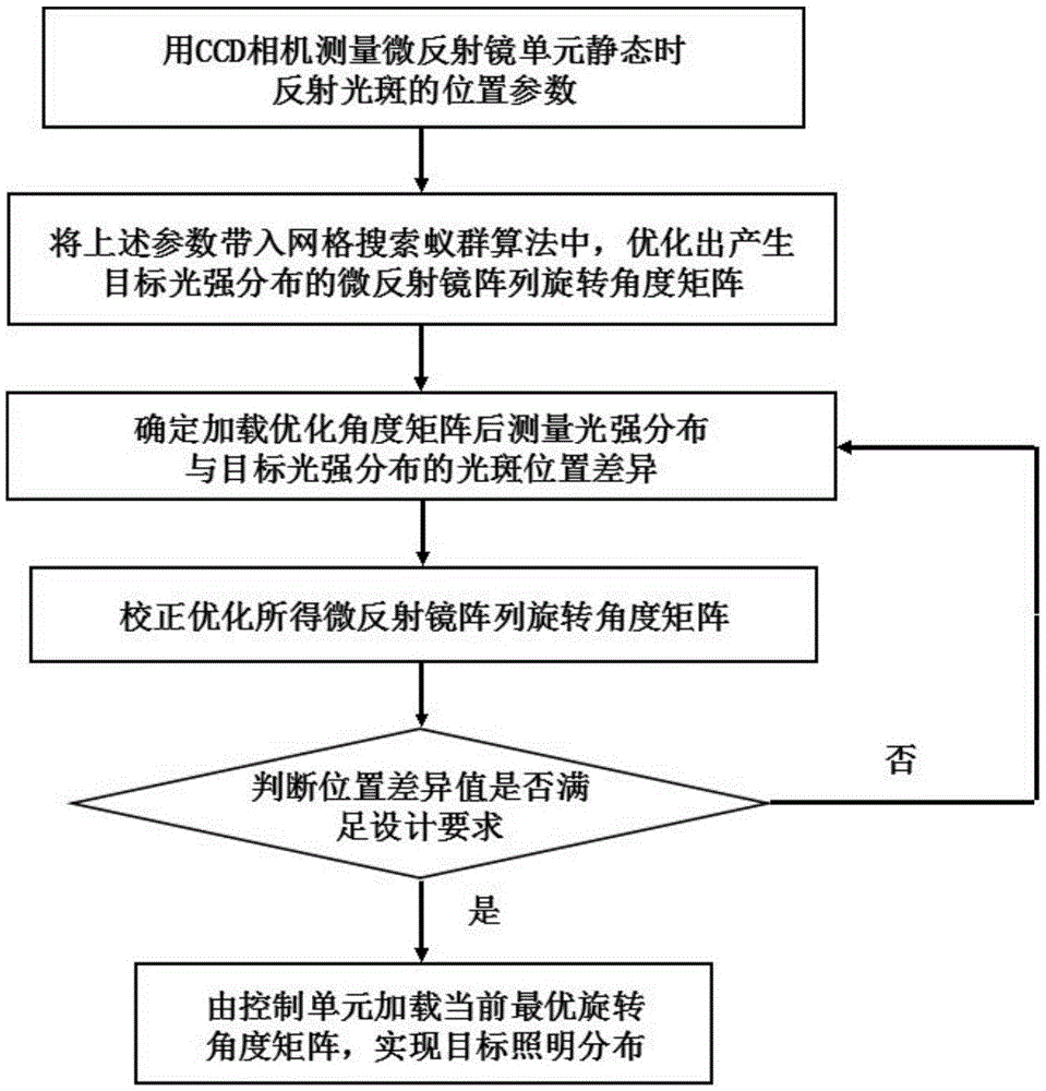
[0074] figure 1 It is a flow chart of the method for realizing a continuously variable free illumination pupil based on a micromirror array of the present invention, including three processes of spot position measurement, spot position optimization, and spot position correction. The specific steps are as follows:

[0075] Step (1), measure the position parameter of the reflected light spot on the illumination target surface when each micro-mirror unit is static with a CCD camera;

[0076] Step (2), bringing the position parameters of the reflected light spot measured in step (1) into the grid search ant colony algorithm, and optimizing the rotation angle matrix of the micromirror array that produces the required light intensity distribution;

[0077] Step (3), utilize the rotation angle matrix that step (2) obtains, generate the control signal of each micromirror to control its angle rotation, measure the light intensity distribution on the illumination target surface at this ...


PUM


Abstract

The invention provides a method for realizing a variable free illumination pupil based on a microreflector array, which includes the steps of spot position measurement, spot position optimization, spot position correction and the like. Among them, the CCD camera measures the position parameters of the reflected light spot when each micro-mirror unit is in a static state; the above parameters are substituted into the grid search ant colony algorithm for optimization, and the rotation angle matrix of the micro-mirror array that produces the required pupil shape is obtained; Calculate the spot position difference between the measured light intensity distribution and the desired light intensity distribution on the target surface after loading the rotation angle matrix, and use it as feedback to correct and optimize the rotation angle of the micromirror array, so that the result finally meets the illumination requirements on the target surface. The invention can realize various lighting modes including non-circumferentially symmetrical complex lighting pupils, has fast optimization speed, good convergence, high accuracy and strong practicability.

Description

technical field [0001] The invention belongs to the field of microlithography, and relates to a method for realizing a free-illumination pupil in a lithography illumination system, in particular to a method for realizing a variable free-illumination pupil based on a microreflector array. Background technique [0002] Microlithography is a technology for manufacturing integrated circuits, liquid crystal displays and other microstructure devices. In lithography, the two factors that play a key role in image quality are resolution and depth of focus, so it is necessary to obtain better resolution to To form graphics of key dimensions, it is necessary to maintain a suitable depth of focus. With the continuous development of lithography technology and the continuous shrinking of lithography nodes, in addition to reducing the exposure wavelength λ and the numerical aperture NA of the projection objective lens, changing the shape of the exposure light source is one of the important...

Claims


Application Information

Patent Timeline
Patent Type & Authority Patents(China)
IPC IPC(8): G03F7/20
Inventor 邢莎莎杜猛廖志杰张海波邢廷文
Owner INST OF OPTICS & ELECTRONICS - CHINESE ACAD OF SCI
Why Eureka
Try Eureka