Passive self-flow control water injection system

A technology of flow control and water injection system, which is applied in nuclear power generation, reactors, and reduction of greenhouse gases. It can solve the problems of large changes in water injection flow before and after stages, inability to cope with injection, and low utilization rate of IVR water sources, etc., to achieve stable injection flow and system The effect of high reliability

Active Publication Date: 2014-10-22
CHINA NUCLEAR POWER TECH RES INST CO LTD +1
View PDF5 Cites 14 Cited by
  • Summary
  • Abstract
  • Description
  • Claims
  • Application Information

AI Technical Summary

Problems solved by technology

[0004] However, in the existing IVR water injection design, either an active injection system supported by an emergency AC power supply is used, which cannot cope with the injection in a situation beyond the design such as a complete loss of AC power supply; The bottom of the tank is directly connected to the pipeline to realize passive IVR water injection without any emergency AC power support. However, in this way, the water injection flow rate changes greatly in the front and back stages, especially in the early stage. The utilization rate of IVR water source is not high

Method used


Image

  • Passive self-flow control water injection system
  • Passive self-flow control water injection system
  • Passive self-flow control water injection system

Examples


Embodiment Construction

[0027] Embodiments of the present invention will now be described with reference to the drawings, in which like reference numerals represent like elements.

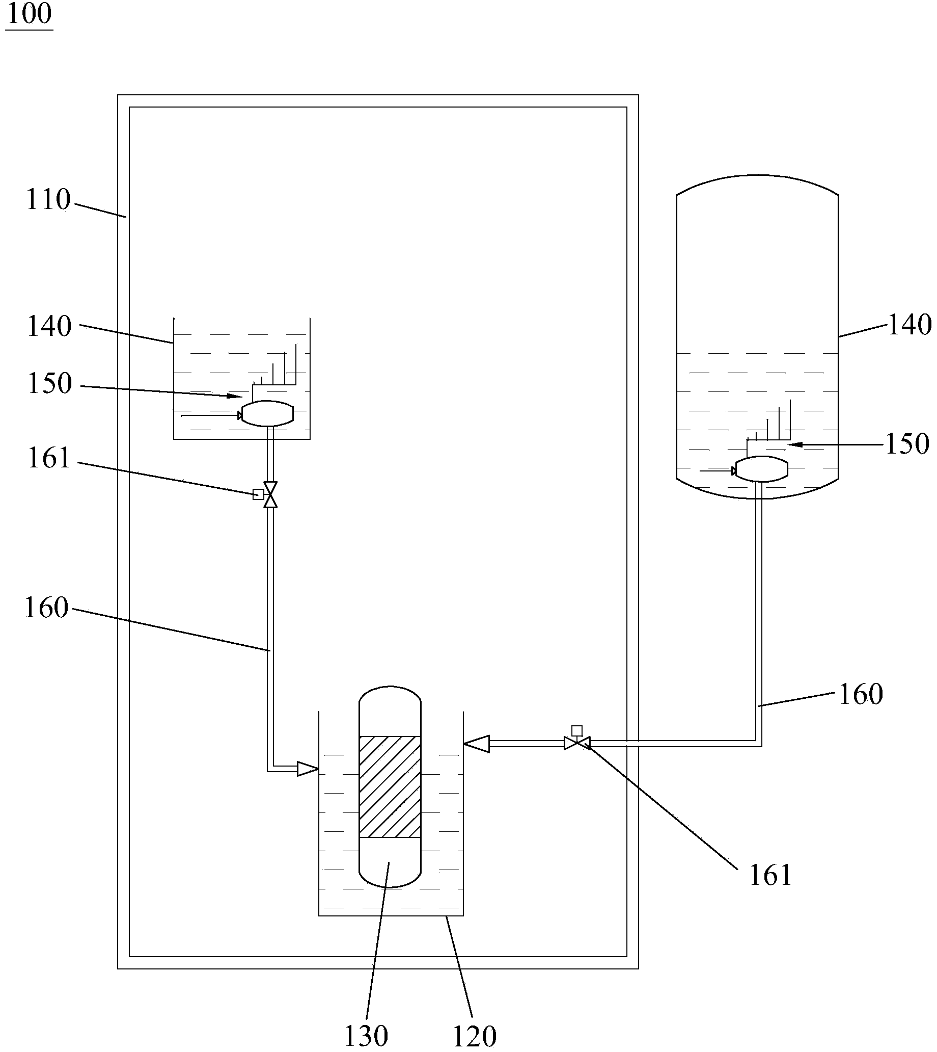
[0028] Such as figure 1 As shown, the passive self-flow control water injection system 100 provided by the present invention is suitable for injecting water into the reactor pit 120 inside the containment vessel 110 , wherein the reactor pit 120 houses a pressure vessel 130 .

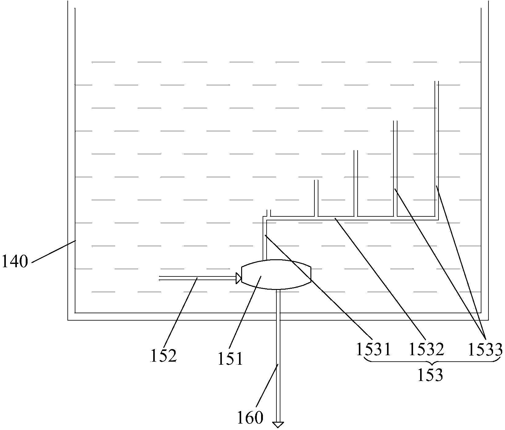
[0029]The passive self-flow control water injection system 100 includes a safety injection tank 140 and a self-flow control device 150, the safety injection tank 140 is arranged inside or outside the containment vessel 110, and the self-flow control device 150 is housed in The safety injection tank 140 is connected to the reactor pit 120 through a water outlet pipe 160; in the event of an accident, driven by the gravity difference or back pressure difference, the cooling water in the safety injection tank 140 passes through the flow control device ...


PUM


Abstract

The invention discloses a passive self-flow control water injection system. The passive self-flow control water injection system comprises a safety injection tank, and a self-flow control device which is received in the safety injection tank and communicated with a reactor pit by use of a water outlet pipe; the self-flow control device comprises a volute chamber, and transverse pipe and vertical pipe assemblies; the volute chamber is of a hollow structure and an outlet is formed in the bottom of the volute chamber; the transverse pipe and vertical pipe assemblies are communicated with the hollow structure of the volute chamber, respectively; the positions in which the vertical pipe assemblies are communicated with the volute chamber and the position of the outlet of the volute chamber are arranged so that cooling water in the safety injection tank flows into the hollow structure of the volute chamber via the transverse pipe and the vertical pipe assemblies and then is swirled, and finally flows out via the outlet; the flow in the vertical pipe assembly is reduced as the liquid level in the safety injection tank is reduced, so that the tangential water flow in the volute chamber is gradually reduced; the intensity of vortex in the volute chamber is automatically regulated, and therefore, the flow resistance on an IVR (In-Vessel Retention) injection pipeline is kept relatively consistent with the variation trend of the injection pressure so that relatively stable injection flow in the entire time period can be ensured; besides, the utilization rate of water injected is increased and the passive self-flow control water injection system does not depend on external power.

Description

technical field [0001] The invention relates to the field of nuclear power plant reactor safety equipment, in particular to a passive self-flow control water injection system suitable for severe accidents of pressurized water reactors. Background technique [0002] The use of nuclear power is a major breakthrough in the history of human energy utilization. Using the fission reaction of atomic nuclei, nuclear power plants can produce high energy output unmatched by all other traditional fossil energy sources, and these high energy outputs often only need to consume a small amount of nuclear fuel. This low-input and high-output feature has made human beings pay more and more attention to the use of nuclear energy, and continue to increase research and development in the field of nuclear energy. Today, nuclear energy has become an important energy component in many countries in the world. However, while nuclear power has extremely high utilization value, it may also bring great...

Claims


Application Information

Patent Timeline
Patent Type & Authority Applications(China)
IPC IPC(8): G21C15/18
CPCY02E30/30
Inventor 曹建华卢冬华傅先刚
Owner CHINA NUCLEAR POWER TECH RES INST CO LTD
Why Eureka
Try Eureka