
Mixed format signal optical fiber transmission device

An optical fiber transmission and signal technology, used in optical fiber transmission, TV systems adapted to optical transmission, cable transmission adaptation, etc., can solve the problem of not being able to meet the real-time transmission, function expansion, and performance upgrade of high-speed image signals and other format signals at the same time. It can solve the problems such as the limitation of performance and the large size of the transmission system, so as to achieve the effect of expanding the temperature adaptation range, reducing the cost and power consumption, and simplifying the data.

Active Publication Date: 2014-10-22
INST OF OPTICS & ELECTRONICS - CHINESE ACAD OF SCI
View PDF5 Cites 45 Cited by
  • Summary
  • Abstract
  • Description
  • Claims
  • Application Information

AI Technical Summary

Problems solved by technology

[0003] At present, the optical fiber transmission equipment at home and abroad is aimed at single-format signal transmission, which cannot satisfy the real-time transmission of high-speed image signals and other format signals at the same time. Disadvantages of being large, expensive and difficult to maintain
At the same time, this type of high-speed optical fiber transmission equipment is generally designed and implemented by application-specific integrated circuits, which are limited in terms of function expansion, performance upgrades, and adaptability to the working environment.

Method used


Image

  • Mixed format signal optical fiber transmission device
  • Mixed format signal optical fiber transmission device
  • Mixed format signal optical fiber transmission device

Examples


Embodiment Construction

[0036] In order to make the purpose, technical solutions and advantages of the embodiments of the present invention clearer, the technical solutions in the embodiments of the present invention will be clearly and completely described below in conjunction with the drawings in the embodiments of the present invention. Obviously, the described embodiments It is a part of embodiments of the present invention, but not all embodiments. Based on the embodiments of the present invention, all other embodiments obtained by persons of ordinary skill in the art without creative efforts fall within the protection scope of the present invention.

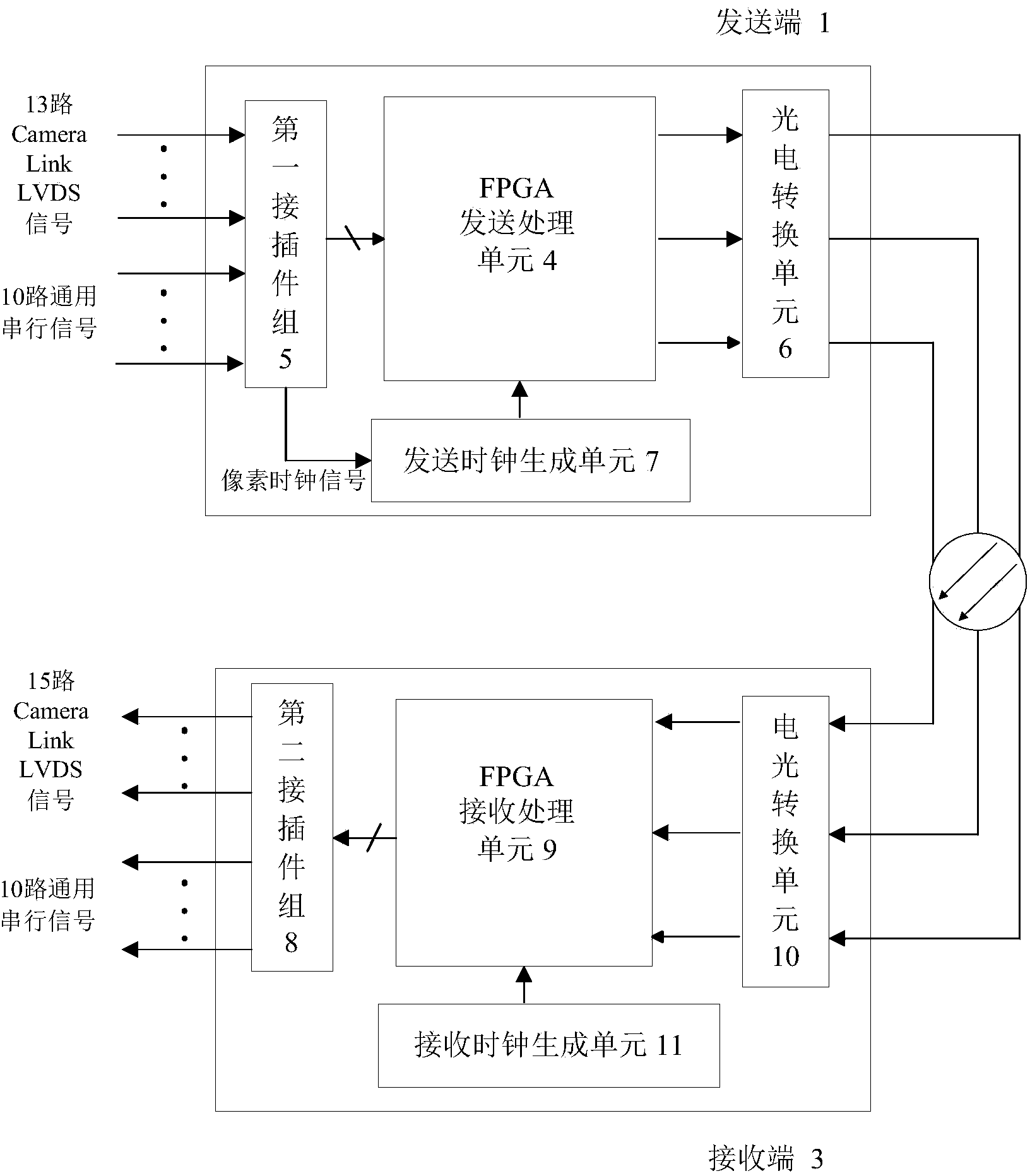
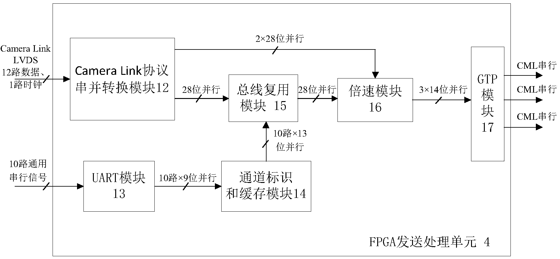
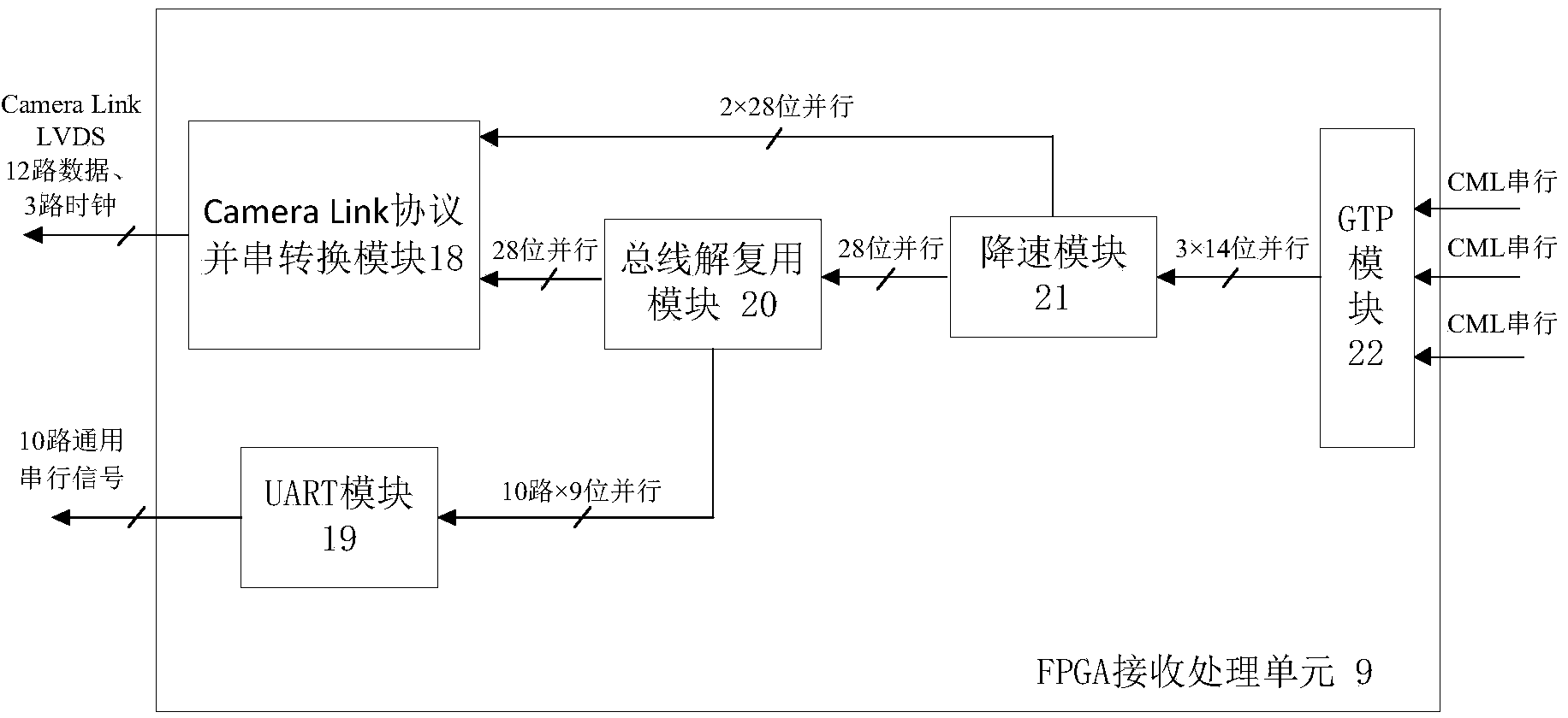
[0037] figure 1 A schematic structural diagram of a mixed-format signal optical fiber transmission device provided by an embodiment of the present invention. Such as figure 1 As shown, the mixed format signal optical fiber transmission device of this embodiment includes a sending end 1, a fiber channel 2 and a receiving end 3; figure 1 As shown...


PUM


Abstract

The invention discloses a mixed format signal optical fiber transmission device. The mixed format signal optical fiber transmission device comprises a sending end, a fiber channel and a receiving end, wherein the sending end converts input camera link format video image signals and multi-channel universal serial signals into optical signals, the optical signals are sent to the receiving end through the fiber channel, and the receiving end receives the optical signals and restores the optical signals to original video image signals and multi-channel universal serial data signals. The mixed format signal optical fiber transmission device is suitable for optical fiber transmission of the camera link video image signals and the multi-channel universal serial signals in all configuration modes, the transmission of mixed format signals in a single-fiber channel at different rates can be achieved through multiplexing of a transmission bus, and consumption of extra fiber channels and devices is reduced. According to the mixed format signal optical fiber transmission device, electrical signal conversion processing and transmission control are achieved through a field programmable gate array (FPGA) device, the requirement for actual functions is met, meanwhile, the usage of application-specific integrated circuits is reduced, the advantage of high integration and universalization degrees can be achieved, and supports can be provided for further function extension and performance upgrading.

Description

technical field [0001] The invention relates to the technical field of signal processing and transmission, in particular to a mixed-format signal optical fiber transmission device. Background technique [0002] With the continuous improvement of frame frequency and resolution, the bandwidth of current video image acquisition equipment can reach the level of gigabits per second (Gbps), and it is difficult for cables to meet the reliable transmission of high-speed video image signals over a distance of ten meters. Optical fiber transmission has the characteristics of high bandwidth, strong anti-electromagnetic interference performance, and long transmission distance. Now it has gradually replaced cables in high-speed and long-distance data transmission applications. [0003] At present, the optical fiber transmission equipment at home and abroad is aimed at the single-format signal transmission, which cannot satisfy the real-time transmission of high-speed image signals and ot...

Claims


Application Information

Patent Timeline
Patent Type & Authority Applications(China)
IPC IPC(8): H04N7/22H04B10/25
Inventor 曾瀚周国忠杜升平安涛
Owner INST OF OPTICS & ELECTRONICS - CHINESE ACAD OF SCI
Learn More