Olefin gas leakage monitoring system and method thereof

A technology of gas leakage and monitoring system, which is used in liquid/vacuum measurement for liquid tightness, measurement device, material analysis by optical means, etc. The overall system, the problem of the leakage location and diffusion status of olefin gas cannot be found intuitively

Inactive Publication Date: 2014-10-29
GR APPL TECH
View PDF6 Cites 11 Cited by
  • Summary
  • Abstract
  • Description
  • Claims
  • Application Information

AI Technical Summary

Problems solved by technology

[0004] Although infrared imaging technology has been used to monitor hazardous gases, for chemical sites, a monitoring system integrating detection and alarm is needed to fully ensure the production safety of chemical sites. Th

Method used


Image

  • Olefin gas leakage monitoring system and method thereof
  • Olefin gas leakage monitoring system and method thereof
  • Olefin gas leakage monitoring system and method thereof

Examples


Embodiment 1

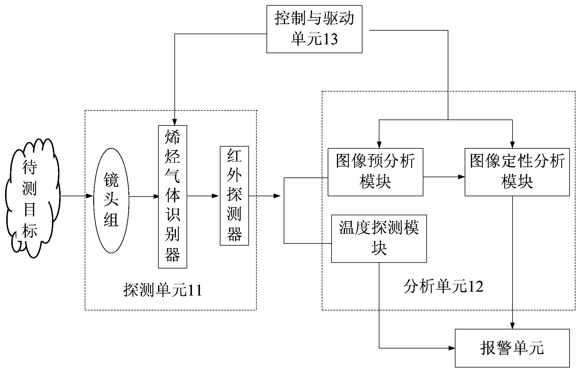
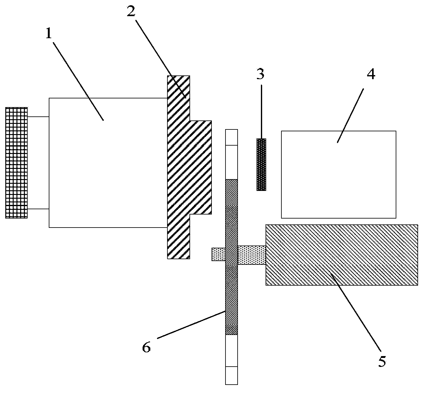
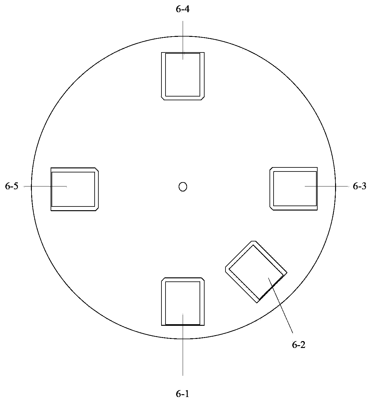
[0040] This embodiment discloses a monitoring system for olefin leakage, figure 1 It is a schematic structural diagram of the monitoring system in this embodiment. Such as figure 1 As shown, the monitoring system includes a detection unit 11, which includes an infrared thermal imager, figure 2 It is a structural schematic diagram of the infrared thermal imager, and the infrared thermal imager includes a lens 1 , a lens interface 2 , an olefin gas identifier 6 , an infrared detector 3 and a processing circuit 4 , and an encoding motor 5 . image 3 It is a top view structure schematic diagram of the olefin gas identifier 6 . Such as image 3 As shown, the olefin gas identifier 6 includes an empty window 6-1, a black body 6-2, and bandpass filters 6-3, 6-4 and 6-5 arranged on the turntable. image 3 Only the case where the olefin gas identifier includes three band-pass filters is shown in , in practice, the olefin gas identifier may include 1-5 band-pass filters. And those ...

Embodiment 2

[0056] This example describes in detail the monitoring method for olefin leakage using the monitoring system in Example 1. Figure 4 A flowchart of the method is shown. First, the thermal imaging camera does not activate the olefin gas identifier, that is, the band-pass filter of the olefin gas identifier is not on the imaging optical path, and the empty window 6-1 of the turntable of the olefin gas identifier faces the infrared detector 3 to detect The target (the target here takes the production site of a chemical industry as an example, but the present invention is not limited thereto) to obtain an infrared image. The advantage of doing this is that the infrared heat radiation energy collected by the lens group is collected as much as possible, and it is unlikely that a single Blocked by the band-pass filter at the beginning, the infrared thermal radiation energy is converted into an electrical signal by the focal plane array, and a clear infrared image is displayed on the ...

Embodiment 3

[0062] This embodiment discloses another monitoring system for olefin leakage. Image 6 A schematic structural diagram of the monitoring system is shown. The monitoring system includes a detection unit, and the detection unit includes an infrared thermal imager, and the infrared thermal imager has the same structure as the infrared thermal imager in Embodiment 1. Including lens, lens interface, olefin gas detector, infrared detector and processing circuit, encoding motor. Under normal conditions, the empty window 6-1 is facing the infrared detector 3, and the olefin gas identifier is not started at this time, that is, the bandpass filter of the olefin gas identifier is not on the optical path of imaging, and the detection target (the target here Taking the production site of a chemical industry as an example, but the present invention is not limited thereto) to obtain infrared images, the advantage of this is that the infrared heat radiation energy collected by the lens group...


PUM


Abstract

An olefin gas leakage monitoring system and a method thereof. The monitoring system contains a detection unit for detecting and imaging an area to be detected, an analytical unit, a control and drive unit and an alarm unit. The detection unit contains an infrared thermal imager which contains an olefin gas recognizer. The analytical unit contains an image preanalysis module and an image qualitative analysis module, wherein the image preanalysis module is used for analyzing an image detected by the detection unit before the olefin gas recognizer is started and judging whether it is a gas; and the image qualitative analysis module is used for recognizing and analyzing the image detected by the detection unit after the olefin gas recognizer is started and judging whether it is an olefin gas. The control and drive unit is connected with the detection unit and the analytical unit and is used for controlling and driving the olefin gas recognizer according to an analysis result of the analytical unit. The monitoring system and the method disclosed in the invention are used for online monitoring of olefin gas leakage. By the system and the method, olefin gas leakage can be detected timely and accurately, and safety and continuity of the production can be guaranteed.

Description

technical field [0001] The invention relates to a monitoring system and method, in particular to a monitoring system and method for olefin gas leakage. Background technique [0002] In the chemical industry, the leakage of olefin gas will bring serious harm, not only affect the production, but also may cause safety accidents, directly threatening the safety of people, so the safety monitoring of the chemical industry has always been widely valued by people. [0003] At present, infrared imaging technology has begun to be widely used in the field of security monitoring. It is usually used to obtain infrared thermal images of objects, and infrared thermal images can carry temperature marking information. According to the performance of the focal plane, the infrared thermal imager can work in two frequency bands: the medium wave frequency band of 3-5 microns and the long wave frequency band of 8-14 microns. Infrared cameras with more than 320×240 pixels can detect most of the ...

Claims


Application Information

Patent Timeline
IPC IPC(8): G01M3/02G01N21/00
Inventor 孟思齐张力黄晓家陈祥初王明会王军
Owner GR APPL TECH
Why Eureka
Try Eureka