Anti-interference narrow-pulse over-voltage detection circuit

A technology of overvoltage detection and narrow pulse, which is applied in the direction of measuring electrical variables, measuring devices, measuring current/voltage, etc., can solve problems such as misjudgment, large duty cycle, and difficulty in realization, so as to avoid misjudgment and work stably Reliable, sample-reducing effects

Inactive Publication Date: 2014-10-29
DIOO MICROCIRCUITS CO LTD
View PDF10 Cites 2 Cited by
  • Summary
  • Abstract
  • Description
  • Claims
  • Application Information

AI Technical Summary

Problems solved by technology

[0005] However, if only one pulse overvoltage is detected and it is considered overvoltage, it is likely to cause misjudgment due to external interference.
Therefore, to truly detect overvoltage, it is necessary to detect multiple consecutive narrow pulse overvoltages, but this requires

Method used


Image

  • Anti-interference narrow-pulse over-voltage detection circuit
  • Anti-interference narrow-pulse over-voltage detection circuit
  • Anti-interference narrow-pulse over-voltage detection circuit

Examples


Embodiment Construction

[0027] The present invention will be described in detail below in combination with specific embodiments.

[0028] see figure 2 Shown is a schematic diagram of the anti-jamming narrow pulse overvoltage detection circuit of the present invention.

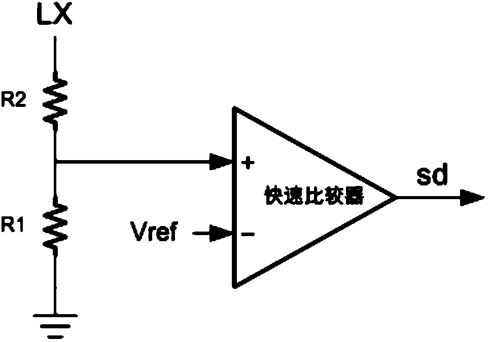
[0029] In this embodiment, the anti-interference narrow pulse overvoltage detection circuit includes a first resistor R1, a second resistor R2, a high-speed comparator 1, a PWM comparator 2, a first RS latch 3, a second RS latch device 4, synchronous counter 5, delay circuit 6, pre-stage drive circuit 7, N-type field effect transistor switch tube NM1, inductor L, Schottky diode Schottky and capacitor C1.

[0030] Wherein, the first resistor R1 and the second resistor R2 are connected in series, one end of the first resistor R1 is grounded, and the middle point of the connection between the first resistor R1 and the second resistor R2 is connected to a non-inverting input terminal of a high-speed comparator 1, the The inverting inpu...


PUM


Abstract

The invention discloses an anti-interference narrow-pulse over-voltage detection circuit. The narrow-pulse over-voltage detection circuit is characterized in that a comparator is connected with the output end of an error amplifier, and the inverting input end of the comparator is connected with a ramp signal; the error amplifier is connected with a second reference voltage, and the inverting input end of the error amplifier is connected with a feedback signal; the R end of a first RS latch is connected with the comparator, and the S end of the RS latch is connected with a clock signal; the R end of a second RS latch is connected with the output end of the comparator and the R end of the first RS latch, the S end of the second RS latch is connected with the output end of a high-speed comparator; the input end of a front-stage driving circuit is connected with the output end of the first RS latch; the front-stage driving circuit is used for driving the grid of an N type field-effect tube switching tube; the grid of the N type field-effect tube switching tube is connected with the output end of the front-stage driving circuit, and the drain of the switching tube is connected with the other end of an inductor; the input end of a delay circuit is connected with the grid of the N type field-effect tube switching tube; one input end of a synchronous counter is connected with the second RS latch, and the other input end of the synchronous counter is connected with the delay circuit; the synchronous counter is used for outputting a turn-off signal.

Description

technical field [0001] The invention relates to a circuit used in a series LED drive or a boost DCDC circuit to detect whether the output is overvoltage through a narrow pulse generated at the LX terminal during boost conversion. Background technique [0002] In the series LED drive circuit or boost DCDC, in some cases, it is necessary to detect whether the output voltage is overvoltage through the LX terminal, so as to shut down the system to protect the chip. [0003] In the DCDC system, especially when the switching current is very large, it is easy to generate various disturbances to the surroundings, and it is inevitable to be disturbed when performing overvoltage detection on the narrow pulse at the LX point. [0004] figure 1 Shown is a traditional overvoltage detection circuit. When the LX terminal voltage is divided by R1 and R2 resistor series, the voltage value exceeds the reference voltage Vref, and the high-speed comparator outputs a shutdown signal sd to shut ...

Claims


Application Information

Patent Timeline
IPC IPC(8): G01R19/17
Inventor 张远斌
Owner DIOO MICROCIRCUITS CO LTD
Why Eureka
Try Eureka