Stub loaded artificial magnetic conductor based high gain microstrip antenna
A technology of artificial magnetic conductor and microstrip antenna, which is applied in the direction of antenna, radiation element structure, electrical components, etc., can solve the problems of inconsistent current intensity distribution, enhance antenna radiation gain, etc., achieve low cost and weight, improve radiation efficiency, Effect of improving electric field intensity distribution
- Summary
- Abstract
- Description
- Claims
- Application Information
AI Technical Summary
Problems solved by technology
Method used
Image

Examples
Embodiment 1
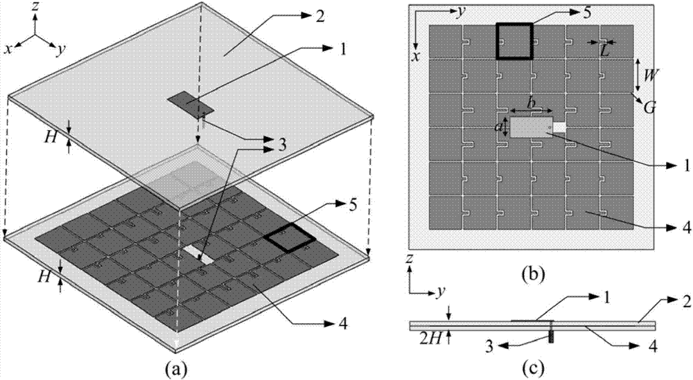
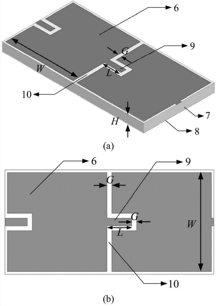
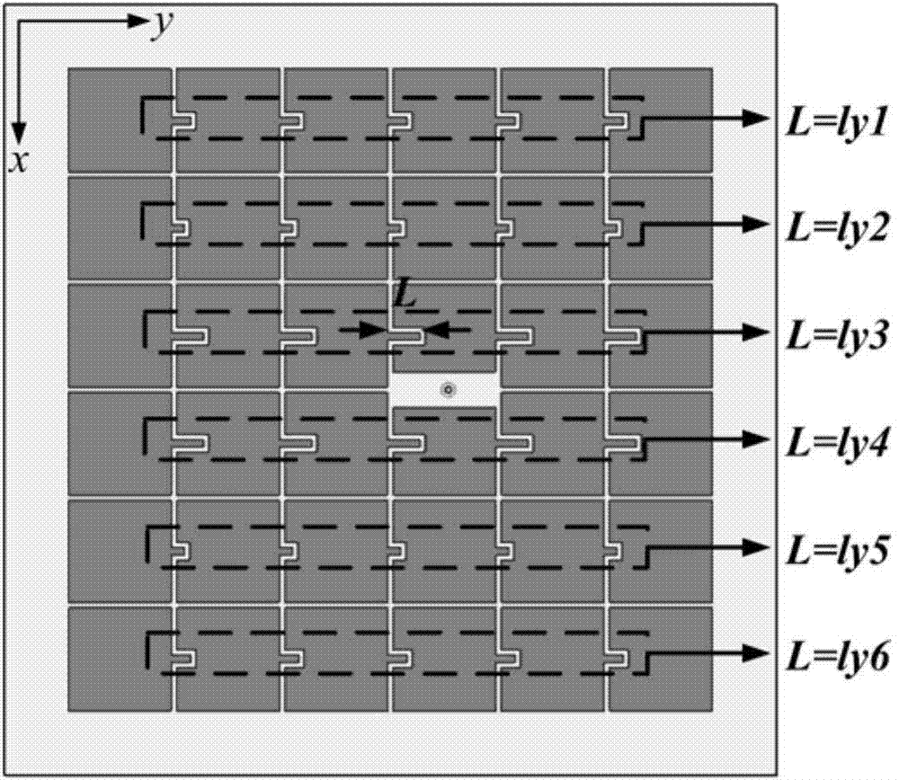
[0032] combine figure 1 and figure 2 , the microstrip antenna includes a rectangular patch antenna 1, a dielectric substrate I[2], a coaxial feeding probe 3 and an artificial magnetic conductor reflector 4 loaded with a branch. The artificial magnetic conductor reflector 4 loaded with branches is composed of 36 artificial magnetic conductor units 5 arranged in a square, and each artificial magnetic conductor unit 5 includes four parts, which are square metal patch 6, dielectric substrate 7, and metal floor 8. Strip metal branch 9. Among them, the length a of the rectangular patch antenna 1 is 5.25mm, and the width b is 10.5mm; the side length W of the square metal patch 6 is 7.8mm, and the length of the strip metal branch 9 is L, which is in the range of 0 to 2.5mm Inside, the width G of the narrow gap 10 is 0.4 mm; the materials of the dielectric substrate I[2] and the dielectric substrate II[7] are both Rogers RT / Duroid5880, and the dielectric constant ε r is 2.2, the di...
PUM
 Abstract
Description
Claims
Application Information
 - R&D
- Intellectual Property
- Life Sciences
- Materials
- Tech Scout
- Unparalleled Data Quality
- Higher Quality Content
- 60% Fewer Hallucinations
Browse by: Latest US Patents, China's latest patents, Technical Efficacy Thesaurus, Application Domain, Technology Topic, Popular Technical Reports.
© 2025 PatSnap. All rights reserved.Legal|Privacy policy|Modern Slavery Act Transparency Statement|Sitemap|About US| Contact US: help@patsnap.com