Heat-dissipating structure of optical module

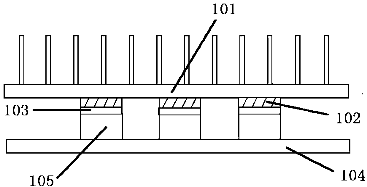
A technology of heat dissipation structure and optical module, which is applied in the direction of cooling/ventilation/heating transformation, etc., which can solve the problems of large compression force of heat conduction pad 102, great influence of heat dissipation, and difficulty in plugging and unplugging, so as to reduce contact thermal resistance and total thermal resistance , easy plug-in effect

Active Publication Date: 2014-10-29
HUAWEI TECH CO LTD
View PDF3 Cites 8 Cited by
  • Summary
  • Abstract
  • Description
  • Claims
  • Application Information

AI Technical Summary

Problems solved by technology

However, the existing heat sink structure has the problems of large thermal resistance and difficulty in plugging and unplugging. Due to the large contact thermal resistance between the base plate 103 and the optical module 105, the thermal conduction resistance of the base plate 103, and the thermal conduction resistance of the thermal pad 102, the The effect of heat dissipation is relatively large, and there is a problem of large thermal resistance; moreover, in order to ensure that the total tolerance of the optical module 105 can be absorbed, it is necessary to use a thicker thermal pad 102, so that the compression force of the thermal pad 102 is very large, and it is easy to plug and unplug. The problem of difficult plugging and unplugging of the optical module 105 with a large amount of compression

Method used


Image

  • Heat-dissipating structure of optical module
  • Heat-dissipating structure of optical module
  • Heat-dissipating structure of optical module

Examples


Embodiment 1

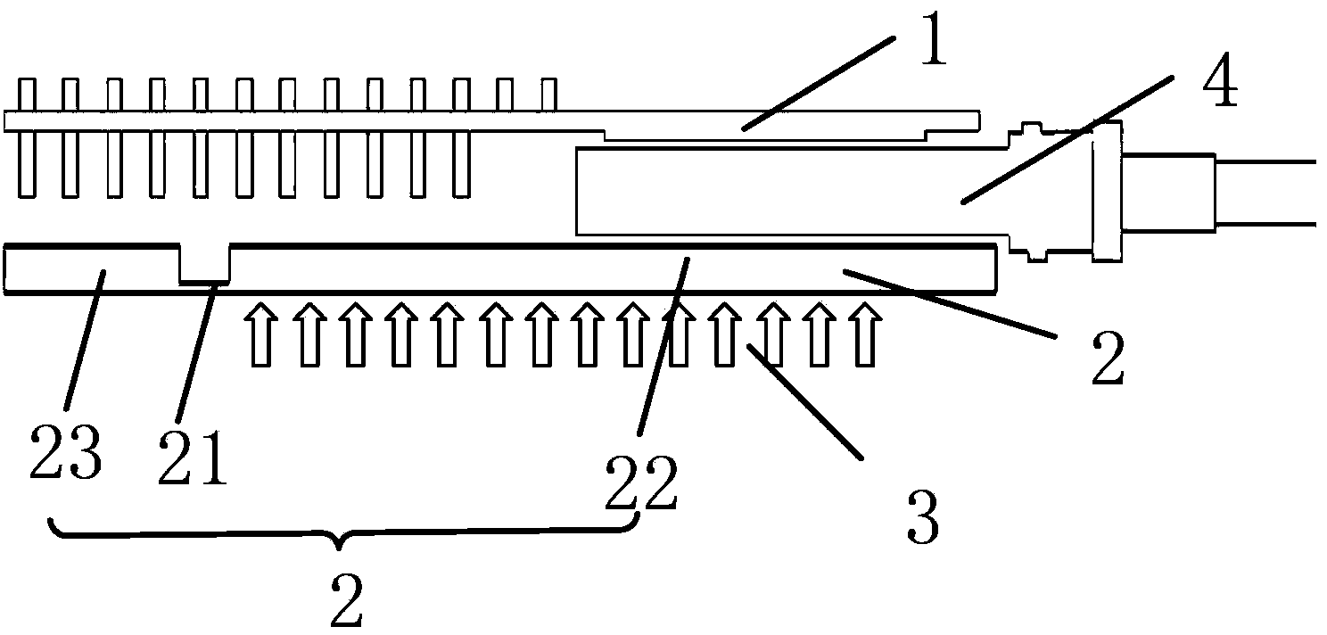
[0026] image 3 is a schematic diagram of the heat dissipation structure of the optical module provided in this embodiment, such as image 3 As shown, the heat dissipation structure of the optical module of the present invention includes: a heat sink 1 , a circuit board 2 and an elastic component 3 . The radiator 1 is fixed on the circuit board 2 by studs and screws. The optical module 4 is pluggably placed between the radiator 1 and the circuit board 2 . The circuit board 2 includes a flexible connection structure 21, a circuit board 22 occupied by the optical module 4, and a circuit board 23 adjacent to the circuit board 22 in the corresponding area of ​​the optical module 4, and a circuit board 23 adjacent to the circuit board 22 in the corresponding area of ​​the optical module 4 The flexible connection structure 21 is used to connect them, so that the circuit board 22 in the corresponding area of ​​the optical module 4 can move up and down.

[0027] Normally, the dista...

Embodiment 2

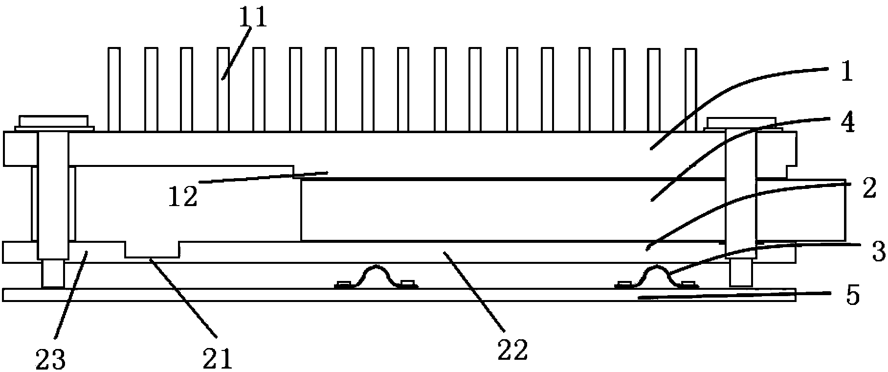
[0036] Figure 4 is a schematic diagram of the heat dissipation structure of the optical module provided in this embodiment, such as Figure 4As shown, the heat dissipation structure of the optical module of the present invention includes: a heat sink 1 , a circuit board 2 and an elastic component 3 .

[0037] The heat dissipation structure of the optical module of this embodiment is basically the same as that of Embodiment 1. The difference is that in this embodiment, the elastic component 3 and the fireproof board 5 are integrally structured, and the fireproof board 5 is a thin metal plate. , the shrapnel can be punched out on the fireproof board 5 through a stamping process, which has a certain degree of elasticity.

[0038] When the optical module 4 is inserted, the shrapnel punched on the fireproof board 5 is deformed under pressure, and the elastic force generated by the shrapnel ensures good contact between the optical module 4 and the boss 12 of the heat sink 1 .

[...


PUM


Abstract

The invention relates to a heat-dissipating structure of an optical module. The heat-dissipating structure comprises a radiator, a circuit board and an elastic component. The radiator is fixedly arranged on the circuit board. The optical module is pluggably arranged between the radiator and the circuit board. The circuit board area occupied by the optical module and the circuit board area adjacent to the circuit board area occupied by the optical module are connected through a flexible connection structure, so that the circuit board corresponding to the optical module can move along the vertical direction of the plane where the circuit board locates independently. The elastic component is arranged at the side, opposite to the optical module, of the circuit board. When the optical module is inserted, the circuit board is pressed by the optical module and moves to the direction of the elastic component; and the elastic component is then pressed to generate elastic force to enable the optical module to be in close contact with the radiator. The heat-dissipating structure of the optical module provided in the invention is small in thermal resistance, easy to insert and unplug, and can enable the optical module to dissipate heat well.

Description

technical field [0001] The invention relates to the field of communication equipment, in particular to a heat dissipation structure of an optical module. Background technique [0002] An optical module is an integrated module that converts optical signals into electrical signals and / or converts electrical signals into optical signals, and plays an important role in the process of optical fiber communication. The optical module will generate a lot of heat when it is working. The laser used to generate or receive optical signals in the optical module has relatively strict temperature requirements. In order to ensure the normal operation of optical communication, the heat generated by the optical module needs to be dissipated in time. However, as the business volume of single boards of network products increases, the high-density layout of optical modules on single boards results in cascading optical module heat dissipation problems. [0003] The existing heat dissipation stru...

Claims


Application Information

Patent Timeline
IPC IPC(8): H05K7/20
Inventor 张军王清云李松林杨右权
Owner HUAWEI TECH CO LTD
Why Eureka
Try Eureka