Piston cooling device and cylinder liner

A cooling device and cylinder liner technology, applied in the field of cylinder liners, can solve the problems of long spray distance and unfavorable cooling system

Active Publication Date: 2014-10-29
WARTSILA FINLAND OY
View PDF5 Cites 3 Cited by
  • Summary
  • Abstract
  • Description
  • Claims
  • Application Information

AI Technical Summary

Problems solved by technology

The disadvantage of this piston cooling device is that the injection distance is relatively long, which has a negative effect on the function of the cooling system
Cooling was also a challenge to execute due to the limited space within the engine block and especially below the cylinders due to the moving connecting rods and counterweights

Method used


Image

  • Piston cooling device and cylinder liner
  • Piston cooling device and cylinder liner
  • Piston cooling device and cylinder liner

Examples


Embodiment Construction

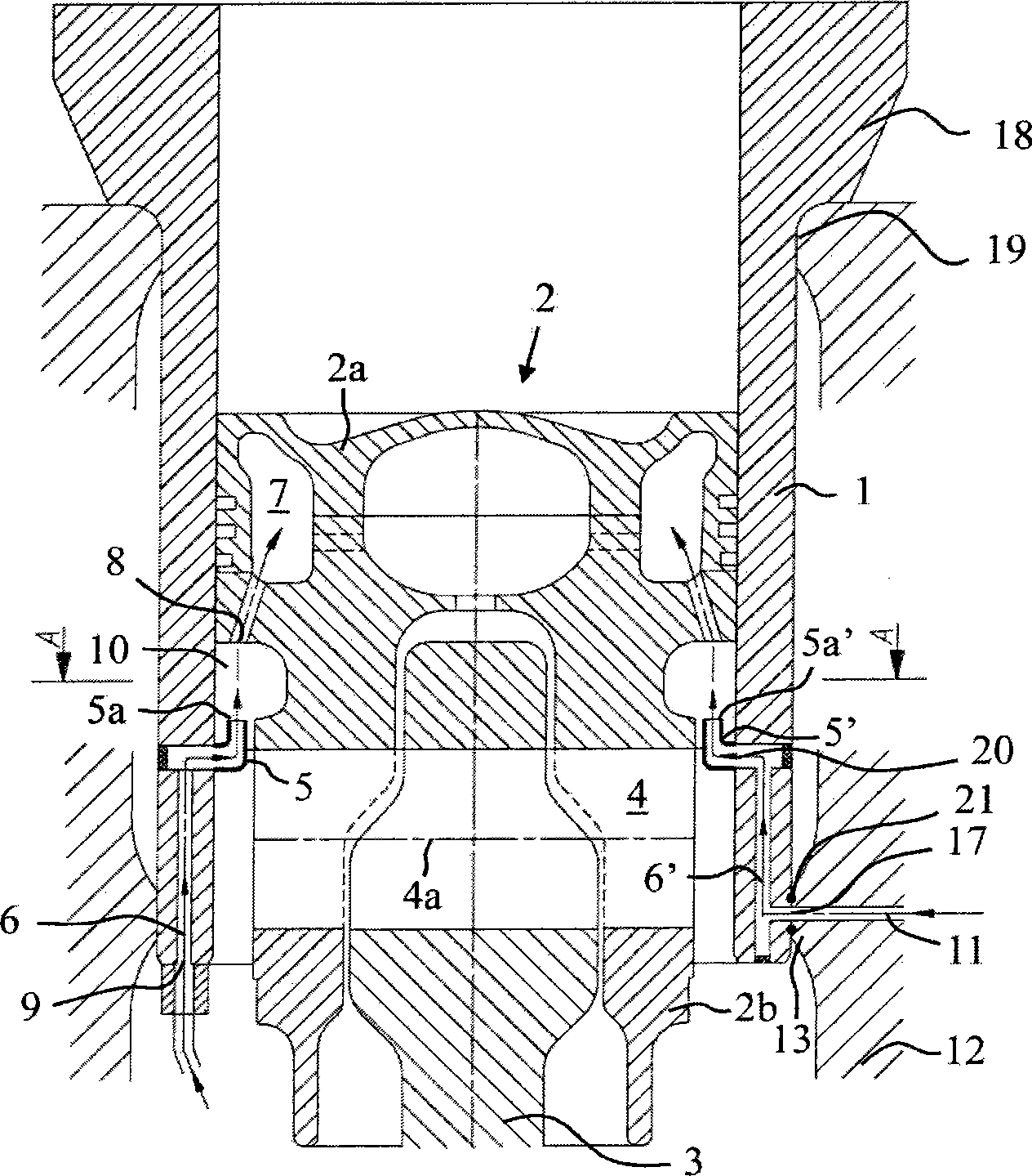
[0019] Embodiments of the present invention will now be described in more detail with reference to the accompanying drawings.

[0020] figure 1 A cooling device for a reciprocating piston 2 of an internal combustion engine according to an embodiment of the invention is shown in . figure 1 , piston 2 is at bottom dead center. Engines using piston cooling are large medium or high speed internal combustion engines. The engine can be used, for example, as the main or auxiliary engine in a boat or in a power plant for generating electric power. The engine may have any reasonable number of cylinders, which may, for example, be arranged in an inline or V configuration. Each cylinder of the engine is provided with a cylinder liner 1 . The cylinder liner 1 is arranged in an engine block 12 . The upper end of the cylinder liner 1 is provided with a collar 1 which leans against the upper surface of the engine block 12 . The engine block 12 includes a protrusion 19 extending towards...


PUM


Abstract

The cooling arrangement for a reciprocating piston (2) of an internal combustion engine comprises a cooling medium injector (5, 5') for injecting cooling oil into a space (10) between the piston (2) and the cylinder liner (1) below the piston crown (2a), an opening (8) for introducing the cooling oil from the space (10) below the piston crown (2a) into a cooling oil gallery (7), and a cooling medium duct (6, 6') for supplying the cooling oil to the cooling medium injector (5, 5,). The cooling medium injector (5, 5') is arranged inside the cylinder at such a height that the tip (5a, 5a') of the injector (5, 5') is above the center axis (4a) of the gudgeon pin (4) of the piston (2) when the piston (2) is at bottom dead center.

Description

technical field [0001] The invention relates to a cooling device for a reciprocating piston of an internal combustion engine according to the preamble of claim 1 . The invention also relates to a cylinder liner for a piston engine according to the preamble of another independent claim. Background technique [0002] In large medium speed engines, piston cooling is typically performed by drilling holes in the crankshaft, connecting rods and piston pins. In high speed engines, piston cooling is usually performed using oil injection. Ejection cooling is also advantageous in medium speed engines as it omits the need for oil drilling in the crank gear components and thus allows higher loads and lower manufacturing costs. In a typical jet cooling arrangement, the cooling arrangement is provided with a separate lubricating oil system for piston cooling. Oil injection nozzles for atomizing cooling oil are arranged in the engine block. Via spray nozzles, oil is sprayed onto the un...

Claims


Application Information

Patent Timeline
Patent Type & Authority Applications(China)
IPC IPC(8): F02F1/00F02F1/16F02F3/22F01P3/02F01P3/06
CPCF01P3/10F02F1/16F02F1/004F02F3/22F01M1/08F01P3/06F02F3/16F02F3/225
Inventor H·努尔米J·库伊图宁
Owner WARTSILA FINLAND OY
Why Eureka
Try Eureka