Stator core for motor
A stator core and tooth technology, which is applied to magnetic circuits characterized by magnetic materials, magnetic circuit shape/style/structure, manufacturing motor generators, etc., can solve the problem of increased number of parts, cumbersome assembly and parts management, etc. problem, to achieve the effect of easy parts management
- Summary
- Abstract
- Description
- Claims
- Application Information
AI Technical Summary
Problems solved by technology
Method used
Image
Examples
Embodiment 1
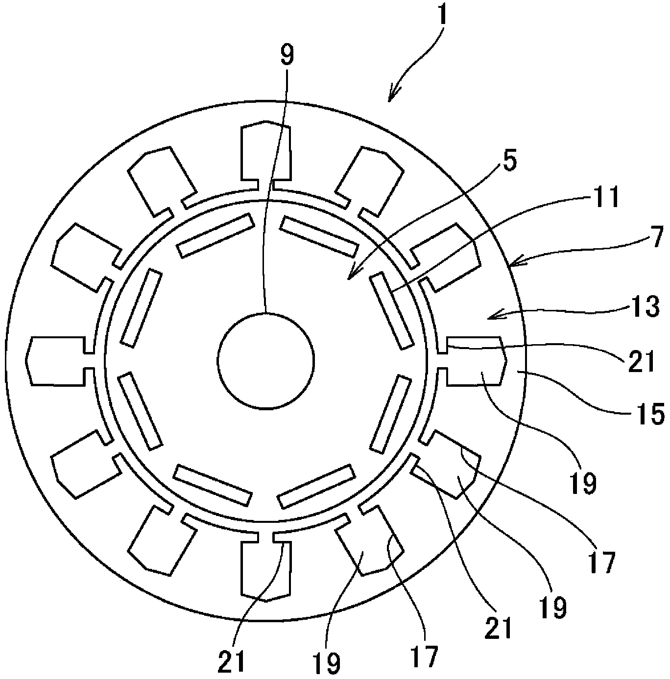
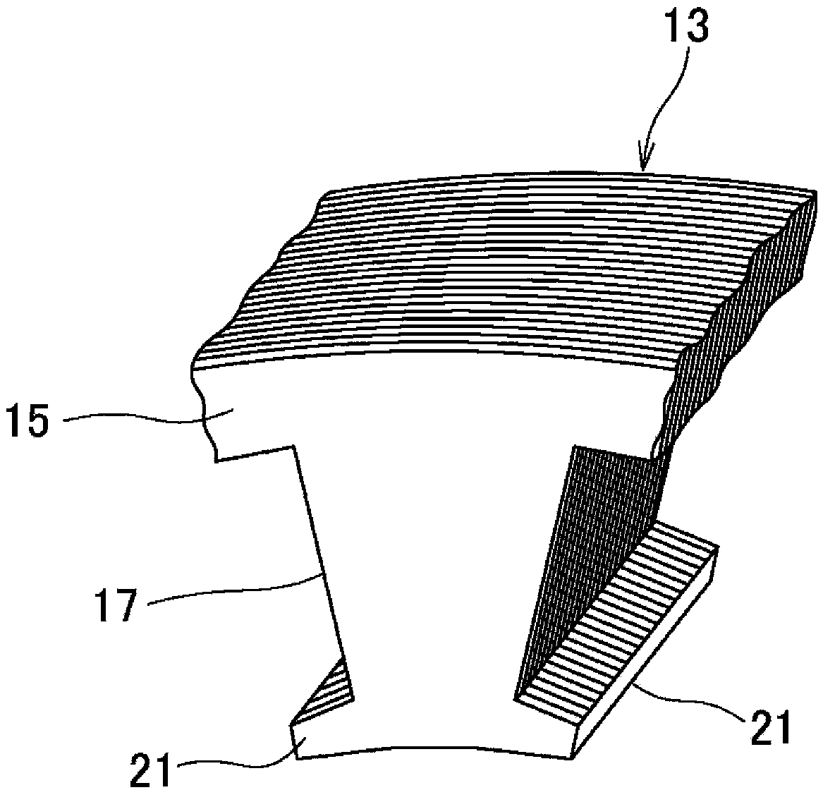
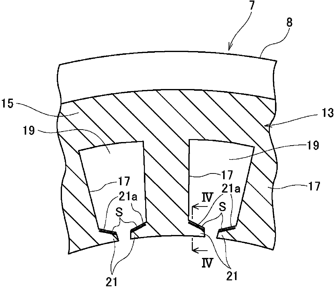
[0025] figure 1 It is a schematic structural diagram showing an electric motor, figure 2 It is a perspective view of main parts showing lamination of a stator core, image 3 is the front view of the main part of the stator core, Figure 4 yes image 3 Sectional view of line IV-IV. In the following description, the circumferential direction and the radial direction mean the circumferential direction and the radial direction of the stator core. In addition, the circumferential direction is also the direction in which the rotor rotates.
[0026] Such as Figure 1 ~ Figure 4 As shown, the electric motor 1 includes a rotor 5 and a stator 7 . The rotor 5 is attached to a rotating shaft 9 . The stator 7 is arranged such that its inner peripheral surface faces the outer peripheral surface of the rotor 5, and constitutes a three-phase AC motor.
[0027] The rotor 5 has a structure in which a plurality of electromagnetic steel sheets are stacked in a ring shape by punching, and...
Embodiment 2
[0045] Figure 6 It relates to Example 2, and is a front view of main parts of the stator core. In addition, since the basic structure is the same as that of Embodiment 1, the same reference numerals are attached to the same constituent parts, and the same reference numerals are assigned to the corresponding constituent parts, and repeated descriptions are omitted.
[0046] In the stator core 13A of the stator 7A of the present embodiment, the non-magnetic portion M is formed on the coil side 21 a of the flange portion 21 . The non-magnetic portion M is a so-called retained austenite phase that is stable at high temperature in carbon steel and remains at room temperature due to rapid cooling. Formed by gas carburizing and quenching. In addition, a solid carburizing agent is applied at a target position so as to be formed by quenching in a non-oxidizing atmosphere. In addition, it may be formed by applying a solid carburizing agent to the target position or by high-frequency...
Embodiment 3
[0050] Figure 7 It is the front view of the stator core segment. In addition, the basic structure is the same as that of the first embodiment, and the same components are given the same reference numerals, and the corresponding components are given the same reference signs B, and redundant descriptions are omitted.
[0051] The stator core 13B of the stator 7B of the present embodiment is arranged in an annular shape so as to join the stator core segmented body 27 .
[0052] Each stator core segment 27 has a yoke configuration portion 29 and a tooth portion 31 , and has a structure in which a plurality of electromagnetic steel sheets are formed in a ring shape by, for example, punching. The yoke configuration portion 29 has a structure in which the annular yoke 15B is divided at predetermined intervals in the circumferential direction. A plurality of the stator core segmented bodies 27 are joined in the circumferential direction to form a ring shape, and are attached to the...
PUM
 Abstract
Description
Claims
Application Information
 - R&D
- Intellectual Property
- Life Sciences
- Materials
- Tech Scout
- Unparalleled Data Quality
- Higher Quality Content
- 60% Fewer Hallucinations
Browse by: Latest US Patents, China's latest patents, Technical Efficacy Thesaurus, Application Domain, Technology Topic, Popular Technical Reports.
© 2025 PatSnap. All rights reserved.Legal|Privacy policy|Modern Slavery Act Transparency Statement|Sitemap|About US| Contact US: help@patsnap.com


