
Numerical control lathe

A technology for CNC machine tools and chassis, applied in the field of CNC lathes, can solve the problems of high noise, low processing efficiency, waste of coolant, etc. of the lathe, and achieve the effects of reducing noise, reducing processing costs, and improving work efficiency and processing accuracy.

Inactive Publication Date: 2014-11-05
覃聪
View PDF6 Cites 8 Cited by
  • Summary
  • Abstract
  • Description
  • Claims
  • Application Information

AI Technical Summary

Problems solved by technology

At present, the existing CNC lathes generally use the motor to drive the main shaft to rotate after the gear is changed, which makes the lathes work with a lot of noise, and some lathes have the defect of low processing efficiency due to the chuck; and the coolant is easy to cause Waste, increase the cost of lathe processing

Method used


Image

  • Numerical control lathe

Examples


Embodiment Construction

[0016] The principles and features of the present invention are described below in conjunction with the accompanying drawings, and the examples given are only used to explain the present invention, and are not intended to limit the scope of the present invention.

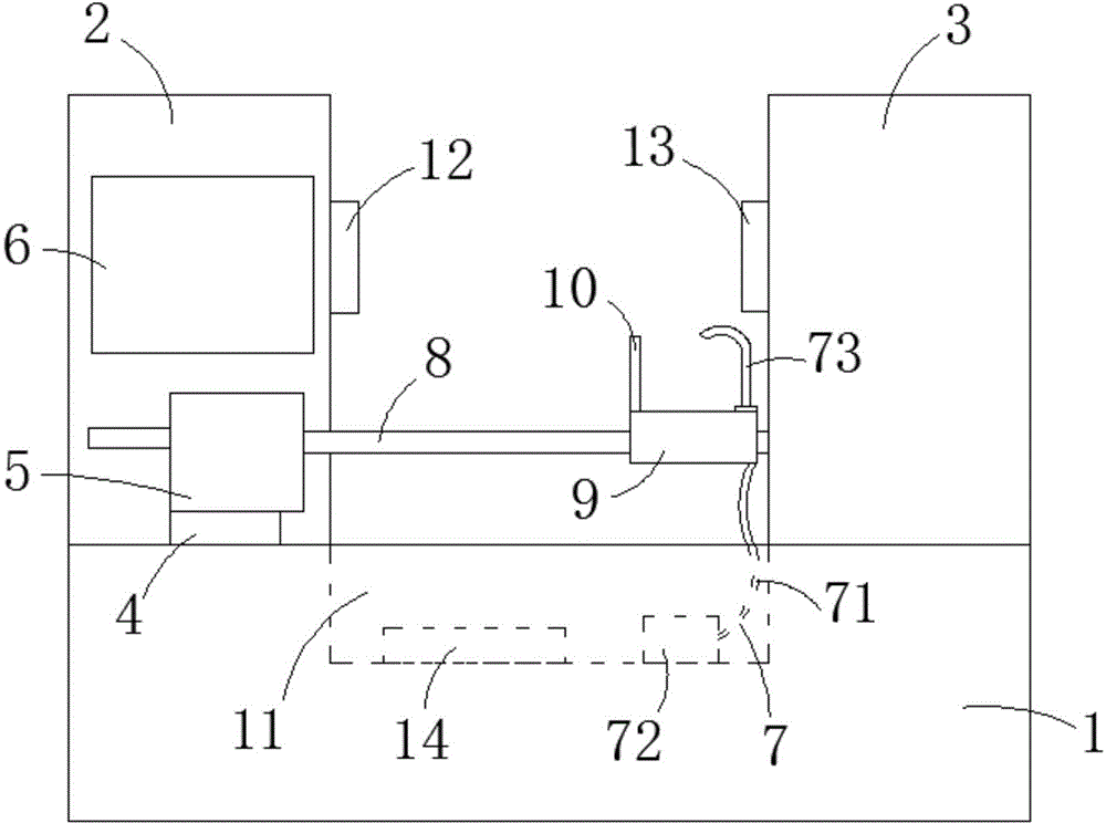
[0017] Such as figure 1 As shown, a numerically controlled machine tool includes a base 1, a first chassis 2, a second chassis 3, a continuously variable transmission 4, a headstock 5, a control device 6 and a coolant recovery device 7, and the first chassis 2 and the second The chassis 3 is respectively placed on both sides of the upper end surface of the base 1, the continuously variable transmission 4 is placed in the lower part of the first chassis 2, the headstock 5 is placed in the first chassis 2 and the stepless The upper end of the stage transmission 4, the control device 6 is placed above the head box 5, the end of the head box 5 close to the second chassis 3 is provided with a rotatable main shaft 8, and ...


PUM


Abstract

The invention relates to a numerical control lathe. The numerical control lathe comprises a base, a first machine box, a second machine box, a continuously variable transmission, a lathe head box, a control device and a cooling liquid recovery device. The first machine box and the second machine box are arranged on the two sides of the upper end surface of the base respectively, the continuously variable transmission is arranged at the lower portion inside the first machine box, the lathe head box is arranged at the upper end of the continuously variable transmission in the first machine box, and the control device is arranged above the lathe head box. A rotary main shaft is arranged at the end, close to the second machine box, of the lathe head box and sleeved with a sliding table capable of sliding in the axial direction of the main shaft, and the sliding table is provided with a turning tool. A waste liquid pool opened upwards is formed in the base, one end of the cooling liquid recovery device is arranged at the upper end of the sliding table, and the other end of the cooling liquid recovery device is arranged in the waste liquid pool. Compared with the prior art, the numerical control lathe has the advantages that the machining noise is low, the machining efficiency is high, cooling liquid can be recycled, and the machining cost can be lowered.

Description

technical field [0001] The invention relates to lathe equipment technology, in particular to a numerically controlled lathe. Background technique [0002] CNC lathe is a high-precision, high-efficiency automatic machine tool. It has a wide range of processing performance, and can process straight cylinders, oblique cylinders, circular arcs and various threads; it has various compensation functions for linear interpolation and circular interpolation, and has played a good role in the mass production of complex parts. economic effect. At present, the existing CNC lathes generally use the motor to drive the main shaft to rotate after the gear is changed, which makes the lathes work with a lot of noise, and some lathes have the defect of low processing efficiency due to the chuck; and the coolant is easy to cause Waste and increase the cost of lathe processing. Contents of the invention [0003] The technical problem to be solved by the present invention is to provide a num...

Claims


Application Information

Patent Timeline
Patent Type & Authority Applications(China)
IPC IPC(8): B23B7/14B23Q11/12
CPCB23B3/30B23Q3/12B23Q5/16B23Q11/1069
Inventor 覃聪
Owner 覃聪
Learn More