Device and method for continuously measuring critical current of high-temperature superconducting tape

A critical current continuous, superconducting strip technology, used in measuring devices, measuring electrical variables, measuring current/voltage, etc., can solve the problem that the strip cannot be used continuously, the measurement value is inaccurate and unintuitive, and it is impossible to know the uniformity of the strip. problems such as performance and defects, to achieve the effect of good engineering practical value, convenient measurement and equipment cost saving

Inactive Publication Date: 2014-11-05
SHANGHAI SUPERCONDUCTOR TECH CO LTD
View PDF8 Cites 13 Cited by
  • Summary
  • Abstract
  • Description
  • Claims
  • Application Information

AI Technical Summary

Problems solved by technology

[0005] At present, the measurement of superconducting long strips, one is to use the welding method, put the solder joints on both ends of the strip, and measure the critical current of the entire strip, so it is impossible to know the information about the uniformity and defects of the strip, and the welding Part of the strip cannot be used any longer; the second is to use the magnetic induction method to measure the critical current of the long strip. This measurement method can only indirectly measure the critical current, and the measured value is inaccurate and unintuitive.

Method used


Image

  • Device and method for continuously measuring critical current of high-temperature superconducting tape

Examples


Embodiment 1

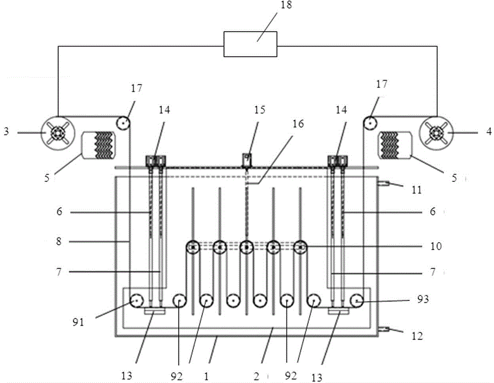
[0064] Step 1. Mount the superconducting tape 8 on the superconducting tape movement mechanism;

[0065] Step 2. The power device 15 drives the lifting mechanism 16 to move up and down, drives the driving wheel 10 to move, and adjusts the length of the superconducting strip 8 between the two measuring components to 1 meter;

[0066] Step 3. Add liquid nitrogen into the liquid nitrogen tank 1 from the liquid inlet 11, so that the liquid surface immerses the superconducting tape in the liquid nitrogen tank 1;

[0067] Step 4. Turn on the stepper motor to drive the superconducting tape 8 to move on the superconducting tape movement mechanism;

[0068] Step 5. Start the power mechanism 14, drive the current terminal 6 and the voltage terminal 7 down, and press the superconducting tape 8 on the bottom plate 13, so that the voltage terminal 7 and the current terminal 6 are in tight contact with the superconducting tape 8;

[0069] Step 6. Turn on the current source, voltage source and calcula...

Embodiment 2

[0074] The method of this embodiment is the same as that of embodiment 1, but the difference is: Step 2. The power device 15 drives the lifting mechanism 16 to move up and down, drives the driving wheel 10 to move, and adjusts the length of the superconducting strip 8 between the two measuring components. Is 2 meters;

[0075] This embodiment can realize the measurement of the critical current uniformity of superconducting tapes at a distance of 2 meters in kilometers.

Embodiment 3

[0077] The method of this embodiment is the same as that of embodiment 1, but the difference is: Step 2. The power device 15 drives the lifting mechanism 16 to move up and down, drives the driving wheel 10 to move, and adjusts the length of the superconducting strip 8 between the two measuring components. Is 5 meters;

[0078] This embodiment can realize the measurement of the critical current uniformity of the superconducting tape with a kilometer level of 5 meters apart.

[0079] The present invention can also measure the current low point or dead point in the superconducting strip to complete defect detection.

[0080] The device of the invention has simple structure, reasonable design and low manufacturing cost, and can realize continuous measurement of critical current of superconducting strips with a length of more than 1 meter, especially for kilometer-level superconducting strips. It can quickly and accurately measure the critical current of the superconducting tape and the ...


PUM


Abstract

A device for continuously measuring the critical current of a superconducting tape comprises a liquid nitrogen tank, a measuring bracket arranged in the liquid nitrogen tank, and a superconducting tape motion mechanism and a measuring mechanism which are arranged on the measuring bracket. The critical current of a superconducting tape is measured by a four-lead method of crimping. A current terminal and a voltage terminal are driven by a power mechanism to move up and down to press the superconducting tape and closely contact the superconducting tape, a current signal and a voltage signal are measured, and the critical current is calculated. The length of the superconducting tape between two measuring points is adjusted by a length adjusting device. A lifting mechanism drives a plurality of driving wheels to move up and down so as to adjust the length of the superconducting tape between the two measuring points. According to the invention, the four-lead method of crimping is adopted to measure the critical current, and the measuring device is compact and simple in structure, convenient to use, and capable of measuring the critical current of a superconducting tape quickly and accurately and obtaining uniformity, defects and other information of a high-temperature superconducting long tape.

Description

Technical field [0001] The invention relates to a measuring device and a measuring method for the critical current of a superconducting strip, in particular to a continuous critical current measuring device and a measuring method. Background technique [0002] In 1911, the Dutch physicist Camerin Onnis discovered that mercury has the "superconductivity" of "zero" resistance at low temperatures, thus ushering in a new era of superconductivity. Now, a whole century has passed, and the development of superconducting materials has been changing with each passing day. Especially after 1986, superconducting materials with high critical temperature (above 77K) have made breakthrough progress, and the practical application of superconducting may be pushed to the liquid nitrogen temperature zone. Great practical significance. Especially since the first generation of Bi 2 Sr 2 Ca 2 Cu 3 O x (Bi-2223, Bi series) and the second-generation high-temperature superconducting material YBa 2 Cu 3...

Claims


Application Information

Patent Timeline
Patent Type & Authority Applications(China)
IPC IPC(8): G01R19/00
Inventor 李贻杰
Owner SHANGHAI SUPERCONDUCTOR TECH CO LTD
Why Eureka
Try Eureka