OTDR (Optical Time-Domain Reflectermeter) control circuit of OLT (Optical Line Terminal) optical module

A technology for controlling circuits and optical modules, applied in electrical components, electromagnetic wave transmission systems, transmission systems, etc., can solve the problems of unstable operation of OLT optical modules, optical interference, and affecting the OTDR detection performance of OLT optical modules.

Active Publication Date: 2014-11-05
APAT OPTOELECTRONICS COMPONENTS
View PDF6 Cites 6 Cited by
  • Summary
  • Abstract
  • Description
  • Claims
  • Application Information

AI Technical Summary

Problems solved by technology

Due to the high price of handheld OTDR equipment, the OTDR functional module has been integrated into the OLT optical module at present. However, the disadvantages of this type of OLT optical module when performing fiber fault testing are: the OTDR detection signal transmitted by the module to the fault point is different from the The OTDR detection signal reflected and scattered back from the fault point will produce optical interference, which will affect the OTDR detection performance of the OLT optical module
The defect of this patented method: when the OLT optical module starts the OTDR detection function, due to the addition of a heating component, the power consumption of the entire OLT optical module will increase the power consumption of two parts in addition to the normal module operating power consumption: The power consumption of the OTDR functional module and the power consumption generated by the heating components. When a network failure occurs, the power consumption of the entire OLT optical module suddenly increases, which will lead to unstable operation of the entire OLT optical module.

Method used


Image

  • OTDR (Optical Time-Domain Reflectermeter) control circuit of OLT (Optical Line Terminal) optical module
  • OTDR (Optical Time-Domain Reflectermeter) control circuit of OLT (Optical Line Terminal) optical module

Examples


Embodiment Construction

[0010] The preferred embodiment of the present invention will be described in detail below in conjunction with the accompanying drawings.

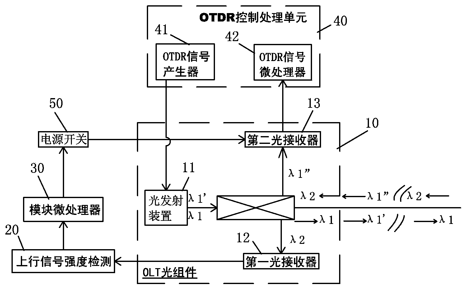
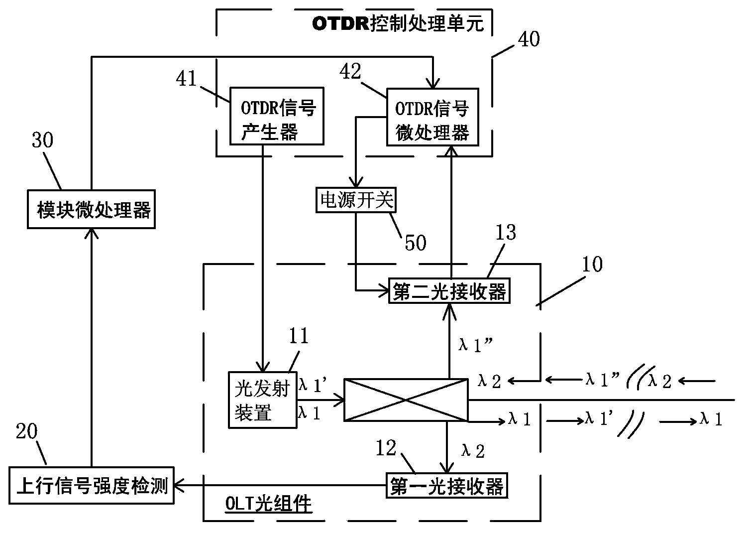
[0011] Such as figure 1 The OTDR control circuit of the shown OLT optical module includes: an OLT optical assembly 10, which assembly includes: an optical emitting device 11 that transmits a downstream optical signal λ1 and an OTDR fault detection signal λ1 ' to the ONU; a first optical receiver 12 receive from the ONU upstream optical signal λ2; a second optical receiver 13 receives the OTDR fault detection signal λ1 "from the network fault point reflection. The input end of an upstream optical signal strength detection 20 is connected with the first optical receiver Device 12 is connected, and its output end is connected to the input end of a module microprocessor 30; An OTDR control processing unit 40, this unit comprises: an OTDR signal generator 41 is connected with described light emitting device 11, an OTDR signal microprocessor 42 ...


PUM


Abstract

The invention provides an OTDR (Optical Time-Domain Reflectermeter) control circuit of an OLT (Optical Line Terminal) optical module. The OTDR control circuit comprises an OLT optical assembly, an OTDR control processing unit, and a power supply switch. The OLT optical assembly comprises an optical transmission device for transmitting a downlink optical signal lambda1 to an ONU (Optical Network Unit) and an OTDR fault detection signal lambda1', a first optical receiver for receiving an uplink optical signal lambda2 from the ONU, and a second optical receiver for receiving the OTDR fault detection signal lambda1' reflected by a network fault point. The input end of an uplink optical signal strength detector is connected with the first optical receiver and the output end is connected with the input end of a module microprocessor. The OTDR control processing unit comprises an OTDR signal generator which is connected with the optical transmission device and an OTDR signal microprocessor of which the input end is connected with the second optical receiver. The output end of the power supply switch is connected with a power supply of the second optical receiver. The power consumption of the OLT module is low when a network is normal, and only increases a little power consumption generated by an OTDR functional block when the network fails, so that the working stability of the OLT optical module is not influenced.

Description

technical field [0001] The invention relates to an OLT optical module of a PON passive optical network system, in particular to an OTDR control circuit of the OLT optical module. Background technique [0002] With the popularization and large-scale application of optical fiber communication technology, the maintenance of optical fiber network has become a problem. Especially when the PON (Passive Optical Network, referred to as PON) network is rapidly developing and expanding, and gradually forming a large-scale application, the maintenance problem of optical fiber and cable is gradually exposed, and has become one of the main problems restricting the development of the industry. If the optical fiber breaks, it is very troublesome to first locate the breakpoint of the optical fiber. It is necessary to send technicians to the site to join hands with the handheld optical time-domain reflectometer OTDR (Optical Time-Domain Reflectermeter, hereinafter referred to as OTDR)....

Claims


Application Information

Patent Timeline
Patent Type & Authority Applications(China)
IPC IPC(8): H04B10/071
Inventor 谢怀堂杨进松
Owner APAT OPTOELECTRONICS COMPONENTS
Why Eureka
Try Eureka