Flattening method and system for fish-eye lens image

A fisheye lens and image technology, applied in the field of image processing, can solve the problems of not getting good results, the image cannot be completely restored, and it is difficult to spread the image on the camera side.

Active Publication Date: 2014-11-05
张家港恩达通讯科技有限公司
View PDF5 Cites 0 Cited by
  • Summary
  • Abstract
  • Description
  • Claims
  • Application Information

AI Technical Summary

Problems solved by technology

Although this scheme can realize the restoration of the fisheye lens image, due to its large amount of calculation, it is mainly used for image processing after the video image is sent back to the computer, and it is difficult to flatten the image on the camera side.
In addition, due to the edge area of ​​the fisheye lens image, such as the a

Method used


Image

  • Flattening method and system for fish-eye lens image
  • Flattening method and system for fish-eye lens image
  • Flattening method and system for fish-eye lens image

Examples


Embodiment 1

[0061] A method for flattening a fisheye lens image is provided in this embodiment, comprising the following steps:

[0062] S1: Calculate the global flattening ratio S c , using the following formula

[0063] S c = x 1 2 f × tan ( x 1 2 f )

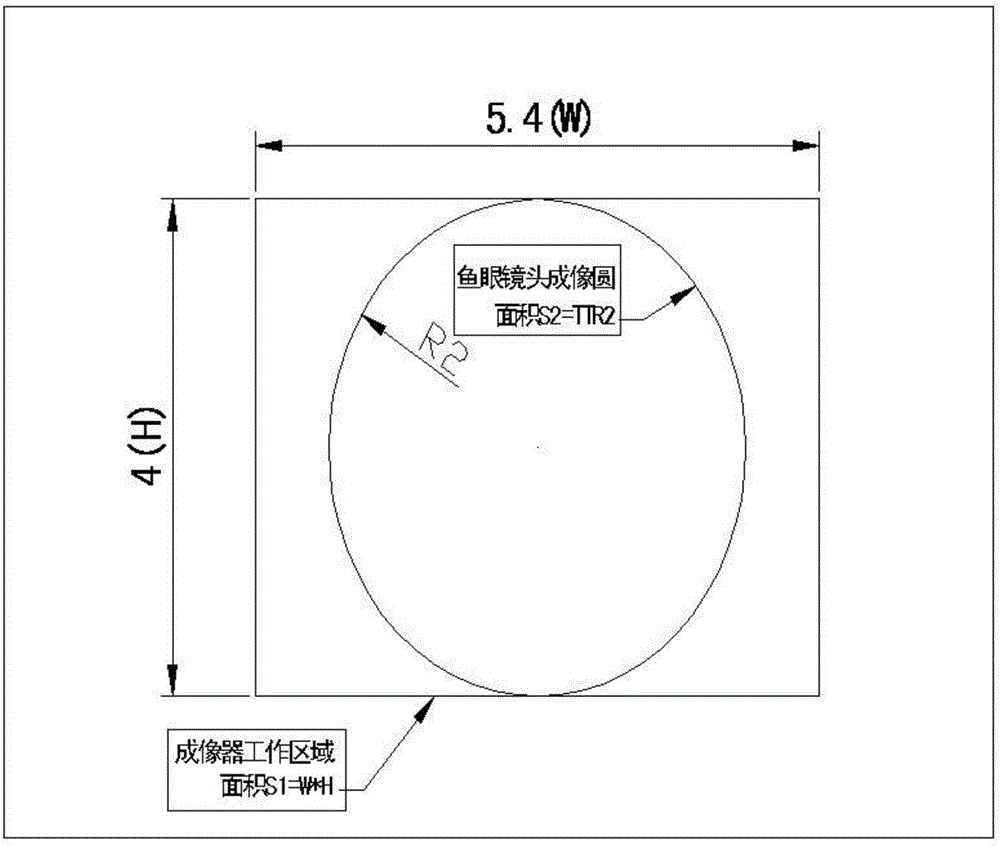
[0064] where x 1 is the effective imaging area width, y 1 is the height of the effective imaging area, and f is the focal length of the fisheye lens;

[0065] S2: For the edge of the effective area of ​​the imager, calculate the point coordinates before flattening, the formula is as follows:

[0066] (x b ,y b ) is the coordinates of points taken on the edge of...

Embodiment 2

[0077] In this embodiment, on the basis of Embodiment 1, after the step S4, a process of correcting systematic errors caused by machining errors is also included. In this way, system errors caused by errors in the production process of the equipment are corrected to improve the accuracy of the processed image.

[0078] Before the step S1, it also includes: configuring the imaging circle of the fisheye lens and the effective area of ​​the imager so that the effective area of ​​the imager is inscribed in the imaging circle of the fisheye lens. Since the effective area of ​​the imager is inscribed in the imaging circle of the fisheye lens, the effective area of ​​the imager can be fully utilized, and there is no waste of the imager. Compared with the setting method in the prior art, the Imager utilization. In addition, the position of the lens relative to the working area of ​​the imager is adjusted by adding an adjustment structure of the lens relative to the imager, so that th...

Embodiment 3

[0081] A method for flattening a fisheye lens image is provided in this embodiment, wherein the image acquisition equipment used includes the following:

[0082] The image sensor is a camera imaging device, used for photoelectric conversion, which converts external optical signals into electrical signals, and the output electrical signals can be converted into signals that can be displayed on the display through the back-end processing circuit.

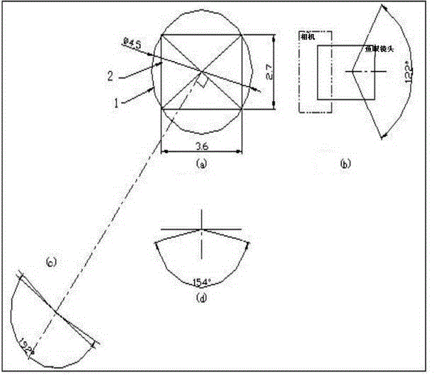
[0083] The field of view refers to the angle at which the lens can collect the most marginal light. According to the long and short sides of the imager, it is divided into horizontal field of view, vertical field of view and diagonal field of view.

[0084] The fisheye lens is a lens designed and processed according to the principle of bionics, imitating the fisheye structure, and the field of view can exceed 180 degrees.

[0085] The panoramic camera has a super large field of view. In order to meet the requirement of simultaneously ...


PUM


Abstract

The invention provides a flattening method for a fish-eye lens image. The method comprises the following steps: specific to the edge of the effective area of an imager, calculating the coordinate of the boundary of the area before flattening; connecting calculated boundary points to obtain a boundary curve, wherein an area inside the boundary curve is taken as a viewing area which can be flattened; and taking a point in the viewing area, and calculating the coordinate value of the point after restoration to obtain a restored image. Through the way, flattening of the fish-eye lens image is realized, a calculation method is simple, flattening of the image can be directly realized at a camera end before image processing, the load of a back-end image processing chip is greatly reduced, and a smooth video can be output.

Description

technical field [0001] The invention relates to an image processing method, in particular to a method and system for flattening a high-definition panoramic camera image. Background technique [0002] With the development of video surveillance products, human's demand for video surveillance has gradually transitioned from the basic conditions of none to the intermediate stage requiring color, dynamic, and continuous, and then deep into high-definition, network, comprehensive, night vision, intelligent analysis, etc. It includes advanced stages of front-end signal acquisition, mid-section signal transmission, and back-end signal storage and display processing. In recent years, the video surveillance industry has maintained rapid growth, and all products and technologies from front-end cameras to back-end display storage are progressing at a high speed. From the city to the suburbs, and then to the countryside; from the long coaxial cable to the optical fiber; from the analog ...

Claims


Application Information

Patent Timeline
IPC IPC(8): H04N5/232H04N7/18
Inventor 张华辉朱忻高坚谈捷
Owner 张家港恩达通讯科技有限公司
Why Eureka
Try Eureka