Metal joint and building structure

A technology for joining metals and components, applied in building structures, buildings, etc., can solve the problems of increasing yield tolerance deviation, damage to joints, strength differences, etc., and achieve the effect of suppressing tolerance deviation, suppressing fracture, and high yield tolerance

Active Publication Date: 2014-11-05
SEKISUI HOUSE KK
View PDF8 Cites 1 Cited by
  • Summary
  • Abstract
  • Description
  • Claims
  • Application Information

AI Technical Summary

Problems solved by technology

[0004] However, in the case of using such joint metal parts, if an excessive load is applied to the joint part, the beam will crack before the metal part deforms, and eventually the beam will break to damage the joint part
In addition, since there are individual differences in the strength of wooden members due to factors such as moisture content, when such joint metal parts are used, the fracture of the wooden member becomes a determining factor of the yield point, and the variation in yield strength and the like becomes large.

Method used


Image

  • Metal joint and building structure
  • Metal joint and building structure
  • Metal joint and building structure

Examples


Embodiment 1

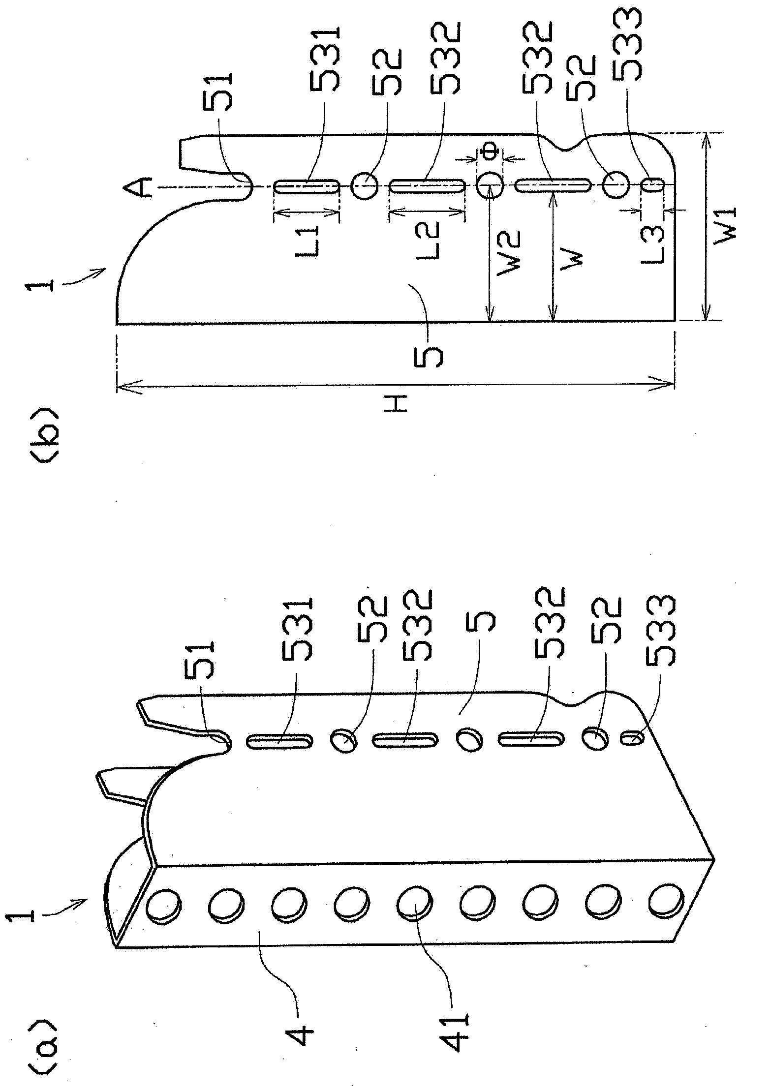
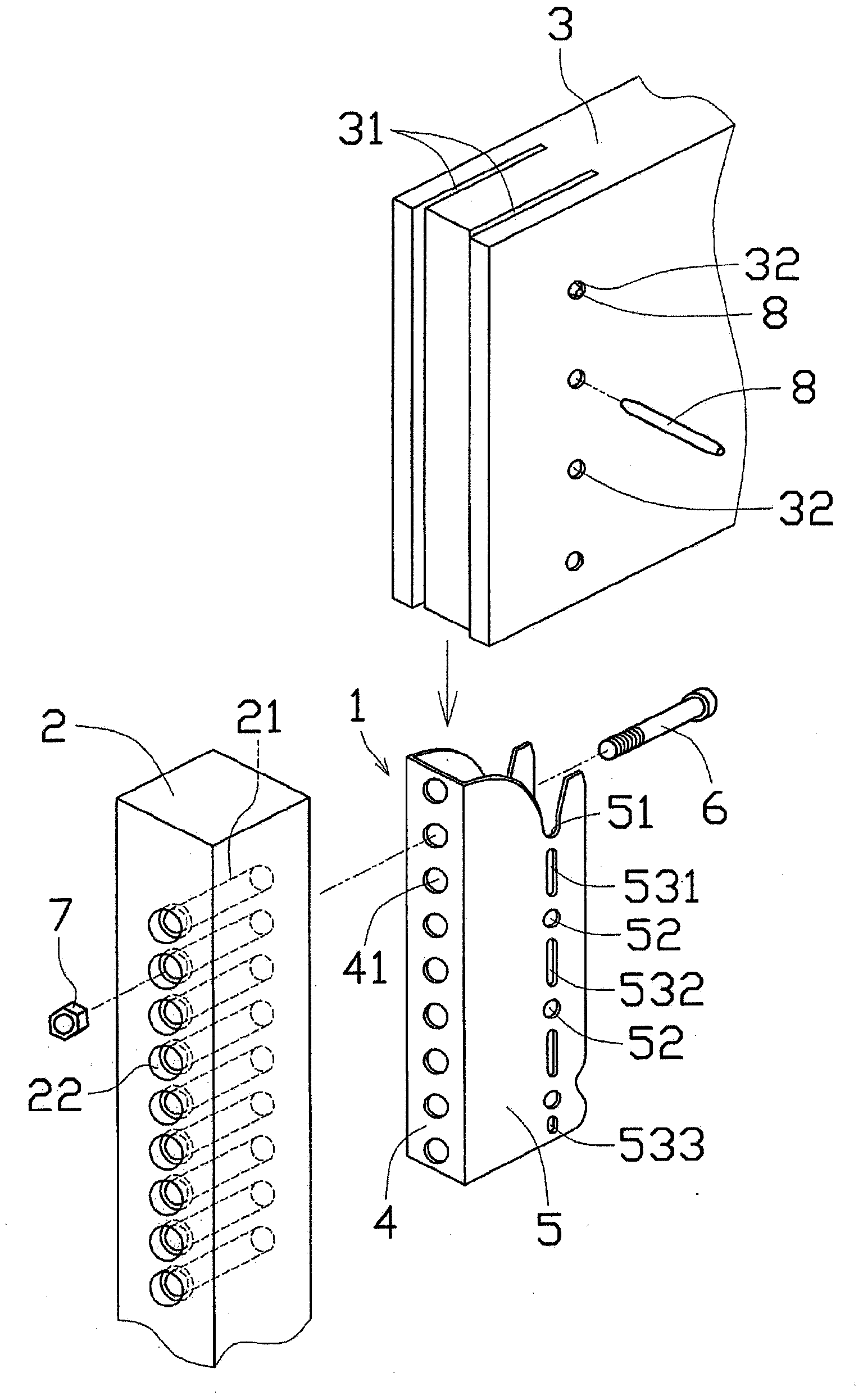
[0098] Example 1 uses figure 1 The illustrated joint metal fitting 1 has a longitudinally long slit-shaped sixth missing portion 531 and second missing portions 532 , 533 formed in the connecting plate 5 . In this metal joint 1, the height H: 266mm, the width W1: 90mm, the diameter Φ of the connecting hole 52: 12.5mm, and the distance W2 from the base end of the connecting plate 5 to the center of the connecting hole 52: 65mm, these values ​​are in The same applies to other Examples 2 and 3 and Comparative Examples 1 and 2. In addition, in the sixth missing part 531 and the second missing part 532, 533, the length L1 of the longitudinal direction of the sixth missing part 531: 31 mm, the length L2 of the longitudinal direction of the second missing part 532: 36 mm, the second missing part The length L3 of the longitudinal direction of 533: 11 mm, and the widths of the sixth missing portion 531 and the second missing portions 532 and 533 are all 6 mm.

Embodiment 2

[0100] like image 3 As shown, in Example 2, a joining metal fitting 1a is used in which arc-shaped first missing portion 54 and fifth missing portion 55 are formed in connecting plate 5a. like Figure 4 As shown, in the first missing portion 54 and the fifth missing portion 55 of the metal joint 1a, the radius of curvature of the outer peripheral portion of the arc shape is 16.25 mm, and the radius of curvature of the inner peripheral portion is 11.25 mm. The first missing portion The distance L4 between 54 is 6 mm, and the distance between the fifth missing portion 55 is also 6 mm.

Embodiment 3

[0102] like Figure 9 As shown, in Example 3, a joint metal fitting 1c having a horizontally elongated slit-shaped seventh missing portion 59 formed continuously with the connecting hole 52 is used. In the seventh missing parts 59a, 59b of the joint metal fitting 1c, the length W3 of the seventh missing part 59a in the lateral direction: 26.65 mm, the length W4 of the seventh missing part 59b in the lateral direction: 6.75 mm, and the seventh missing part The vertical width of 59a, 59b is 6.0 mm.


PUM

PropertyMeasurementUnit
Heightaaaaaaaaaa
Widthaaaaaaaaaa
Diameteraaaaaaaaaa

Abstract

[Problem] To provide a metal joint and building structure that is very reliable and has excellent stability as a junction and that does not lose yield resistance, initial stiffness, energy absorption capacity or the like in the junction when an excessive load is applied at the junction of a support member and horizontal member. [Solution] A metal joint (1) comprising a stationary plate (4) affixed to a side face of a support member (2), and a coupling plate (5), which is provided protruding from the stationary plate (4) toward the side of a horizontal member (3) and which is connected so as to be inserted into grooves (31) formed across the end face of the horizontal member (3) in the vertical direction, wherein the coupling plate (5) is provided with a plurality of coupling holes (52), into which cylindrical coupling instruments (8) are inserted into the grooves (31) so as to pass through the horizontal member (3), and a first cut portion (54) formed by cutting around the coupling holes (52). The first cut portion (54) is formed to be in an arc-shape centered on the coupling hole (52).

Description

technical field [0001] The present invention relates to a joining metal used when joining a cross member to a support member and a building structure using the joint metal to join the support member and the cross member. Background technique [0002] Conventionally, as a method of joining wooden members such as columns and beams in wooden buildings, joining metal parts of various shapes have been used for the purpose of ensuring efficiency in construction, durability of joint parts, and the like. [0003] Such a joint metal fitting has, for example, a front panel fixed in a state of being in contact with the side surface of the column, and a pair of side panels that are bent at both ends of the front panel and protrude toward the beam side to form a U-shape ("オ " is katakana in Japanese) (for example, refer to Patent Document 1). The joining metal piece is arranged up and down in the front panel to form a plurality of front holes for bolts to pass through. Bolts inserted th...

Claims


Application Information

Patent Timeline
IPC IPC(8): E04B1/58E04B1/26
CPCE04B2001/2442E04B1/2604E04B2001/2664E04B2001/2636
Inventor 宇都宫伸治纪本亨田畑治西城戸邦治土方和己广濑辉高桥靖曜
Owner SEKISUI HOUSE KK
Why Eureka
Try Eureka