
On-demand power control system, on-demand power control system program, and computer-readable recording medium on which this program is recorded

A power control system, on-demand technology, applied in the direction of control/regulation system, power network operating system integration, information technology support system, etc., can solve the problems of power reduction, inability to guarantee power reduction rate, no consideration, etc.

Inactive Publication Date: 2014-11-05
NITTO DENKO CORP
View PDF5 Cites 14 Cited by
  • Summary
  • Abstract
  • Description
  • Claims
  • Application Information

AI Technical Summary

Problems solved by technology

In this conventional type of HEMS, attention is paid to the use of electrical equipment, so how much power can be reduced by changing the use of each electrical equipment is not considered, and the power reduction rate that can meet the power saving request cannot be guaranteed.
[0011] In recent years, studies have been made on networking devices in the home based on the Econet standard, but it cannot be said that the power supplied to each electric device is controlled in a finer manner.

Method used


Image

  • On-demand power control system, on-demand power control system program, and computer-readable recording medium on which this program is recorded
  • On-demand power control system, on-demand power control system program, and computer-readable recording medium on which this program is recorded
  • On-demand power control system, on-demand power control system program, and computer-readable recording medium on which this program is recorded

Examples


no. 1 approach

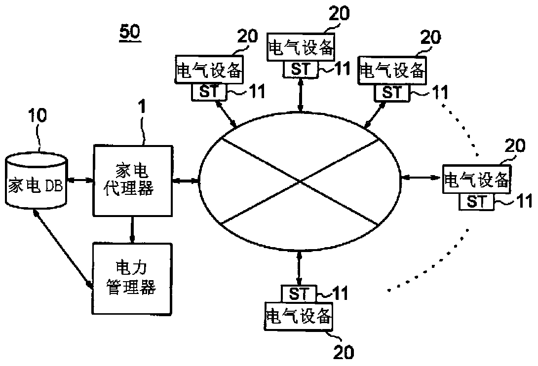
[0286] Figure 8 Yes means figure 1 The illustrated functional block diagram of the first embodiment of the functions included in the power manager.

[0287] Figure 8 The reference numeral 1 of the reference numeral 1 denotes a power manager, the reference numeral 10 denotes its memory, and the reference numeral 11 denotes an ST. The power manager is composed of an initial target value update unit 120 and a power adjustment unit 122. Reference numeral (1) indicates the power consumption transmitted from ST. Furthermore, the power manager converts the above-mentioned power consumption into a power usage plan that determines the power usage of each minimum control interval τ as a preprocessing before its operation, and combines the power usage plan, the instantaneous power of the initial target value, and the maximum instantaneous power The power is stored in the storage 10. Reference numeral (2) denotes a power request message sent from ST, and the power request message is sent...

no. 2 approach

[0405] The above-mentioned dynamic priority control unit 1 can finally control the instantaneous power below the maximum instantaneous power, and can perform control that satisfies the upper limit C (Wh) of the accumulated power. However, when the equipment is used, unexpected changes in the load are caused. The increase in instantaneous power sometimes exceeds the maximum instantaneous power. The second embodiment to deal with this situation will be described.

[0406] Figure 18 It is a functional block diagram of the second embodiment.

[0407] The power manager includes an initial target value update unit 120, a power adjustment unit 122, and a continuous monitoring unit 124.

[0408] The initial target value update unit 120 and the power adjustment unit 122 have the same functions as the above-mentioned units, and therefore the description is omitted.

[0409] The continuous monitoring unit 124 continuously monitors the power consumption, and when the overall power consumption e...

Embodiment 1

[0541] (Condition setting of Example 1 and Example 2)

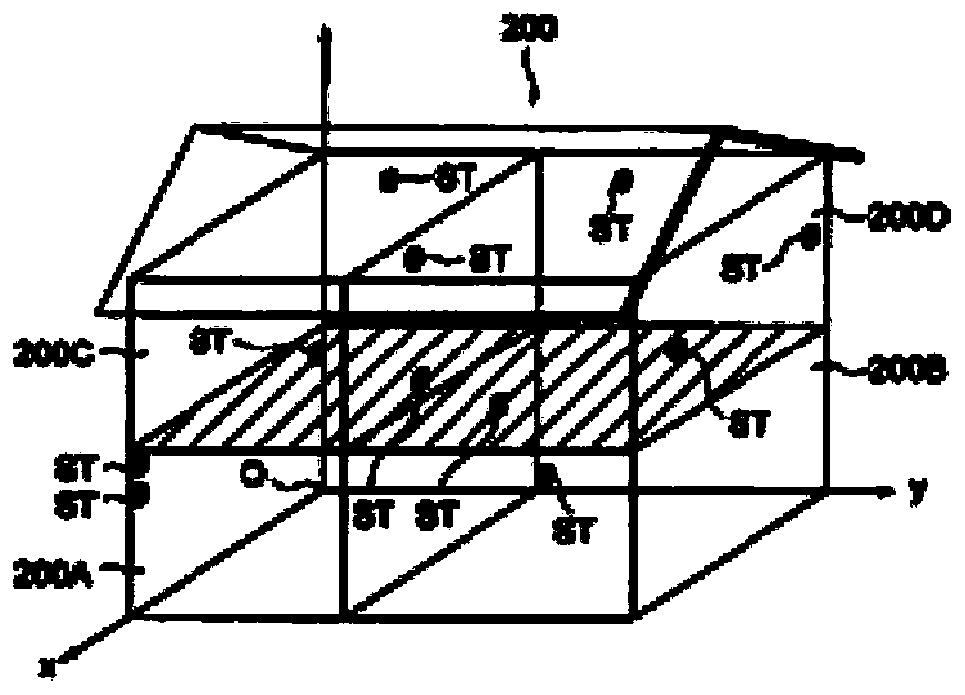
[0542] In the embodiment, in order to obtain data based on real life, experiments were conducted in a smart apartment room. Approximately 20 household appliances used in ordinary life such as refrigerators, washing machines, TVs, air conditioners, and lighting are installed in this smart apartment room of 1DK, and smart connectors are installed in each socket to measure and control their power. In addition, some home appliances have a communication device for acquiring and operating operation and operation function modes, and this communication device is also used.

[0543] In the environment as described above, a home server was set up for data measurement, and all the data that could be measured were recorded and evaluated.

[0544] In this way, experiments were conducted based on the environment. In the simulation experiment, the electric power changes during real life are provided as input, and the EoD protocol is applied ...


PUM


Abstract

To provide an EoD control system which supplies power to electrical devices while changing priorities between the electrical devices according to the states of use by a user instead of predetermined fixed priorities between the electrical devices, which can control supply of power from a commercial power source in real time at a request for power required by the user, and which controls supply of power meeting QoL required in user's daily life, an EoD control system program, and a computer-readable recording medium on which the program is recorded. An on-demand power control system in which dynamic priority control is performed, includes a power source, a plurality of electrical devices, a home appliance agent that controls supply of power to each electrical device by receiving a signal having a power value from a smart tap or each electrical device, by calculating a requested power and a priority on the basis of the received signal, by transmitting the requested power and the priority as a power request message to a power manager, and by transmitting a function control command for controlling the electrical device to the electrical device according to a power assignment message received from the power manager, the power manager that obtains power to be assigned to each electrical device according to the priorities between the electrical devices on the basis of the power request message from the electrical device received from the home appliance agent, and a home appliance DB connected to the power manager and / or the home appliance agent, the home appliance agent, the power manager and the home appliance DB constituting a network connected to the electrical devices through the smart taps, wherein the power manager determines power to be assigned to each electrical device by inquiring the home appliance agent of whether or not the electrical device is capable of adjusting an operating function mode set as a target of a service operation of the electrical device, and of power for the electrical device, wherein if the electrical device is capable of adjusting the operating function mode, the power manager obtains as a power assignment message the operating function mode set as a target for the electrical device and / or a power mode having necessary power and necessary time for reaching the operating function mode as a target, wherein if the electrical device is not capable of adjusting the operating function mode, the power manager obtains a power mode as a power assignment message without considering the operating function mode, and wherein the power manager includes a memory for transmitting the power assignment message thus obtained to the home appliance agent.

Description

Technical field [0001] The present invention relates to an on-demand power control system in a home or office network, a program of an on-demand power control system, and a computer-readable recording medium recording the program, and in detail, to the quality of life that does not impair the user’s daily life. (Quality of Life) (hereinafter referred to as "QoL") that dynamically changes the priority between electrical equipment and controls the power supply in a manner that does not exceed the upper limit of power consumption (Wh), An on-demand power control system program and a computer-readable recording medium recording the program. Background technique [0002] The on-demand power control system is a system used to realize energy management in homes and offices. The system reverses the supply-side “push” power network to a user- and consumer-oriented “ Pull (pull) type" system. The system is the following system: in response to requests for power from various household app...

Claims


Application Information

Patent Timeline
Patent Type & Authority Applications(China)
IPC IPC(8): H02J13/00H02J3/00
CPCH02J13/00H02J3/00Y02B70/3225Y04S20/222Y04S40/124Y04S40/126G05F1/66H02J2310/14H02J13/00009H02J2310/60H02J13/00016H02J13/00026H02J13/00004H02J3/14Y02B90/20Y04S40/121Y04S20/242Y02B70/30
Inventor 松山隆司加藤丈和汤浅健史
Owner NITTO DENKO CORP
Learn More