Control device and method for ac rotary electrical machine, and electrical power steering device

A technology of rotating motors and control devices, which is applied in the field of control and can solve problems such as the inability to maintain smooth rotation

Active Publication Date: 2014-11-05
MITSUBISHI ELECTRIC CORP
View PDF6 Cites 19 Cited by
  • Summary
  • Abstract
  • Description
  • Claims
  • Application Information

AI Technical Summary

Problems solved by technology

[0010] However, for example, since the control device for the AC rotating electrical machine described in the above-mentioned Patent Document 1 has only one set of coils of the AC rotating electrical machine, even if the short-circuit fault location is identified, it is not easy to adjust the current at the short-circuit fault location to a desired value. action, so there is a problem that smooth rotation cannot be maintained due to the generation of braking torque, etc.

Method used


Image

  • Control device and method for ac rotary electrical machine, and electrical power steering device
  • Control device and method for ac rotary electrical machine, and electrical power steering device
  • Control device and method for ac rotary electrical machine, and electrical power steering device

Examples


Embodiment approach 1

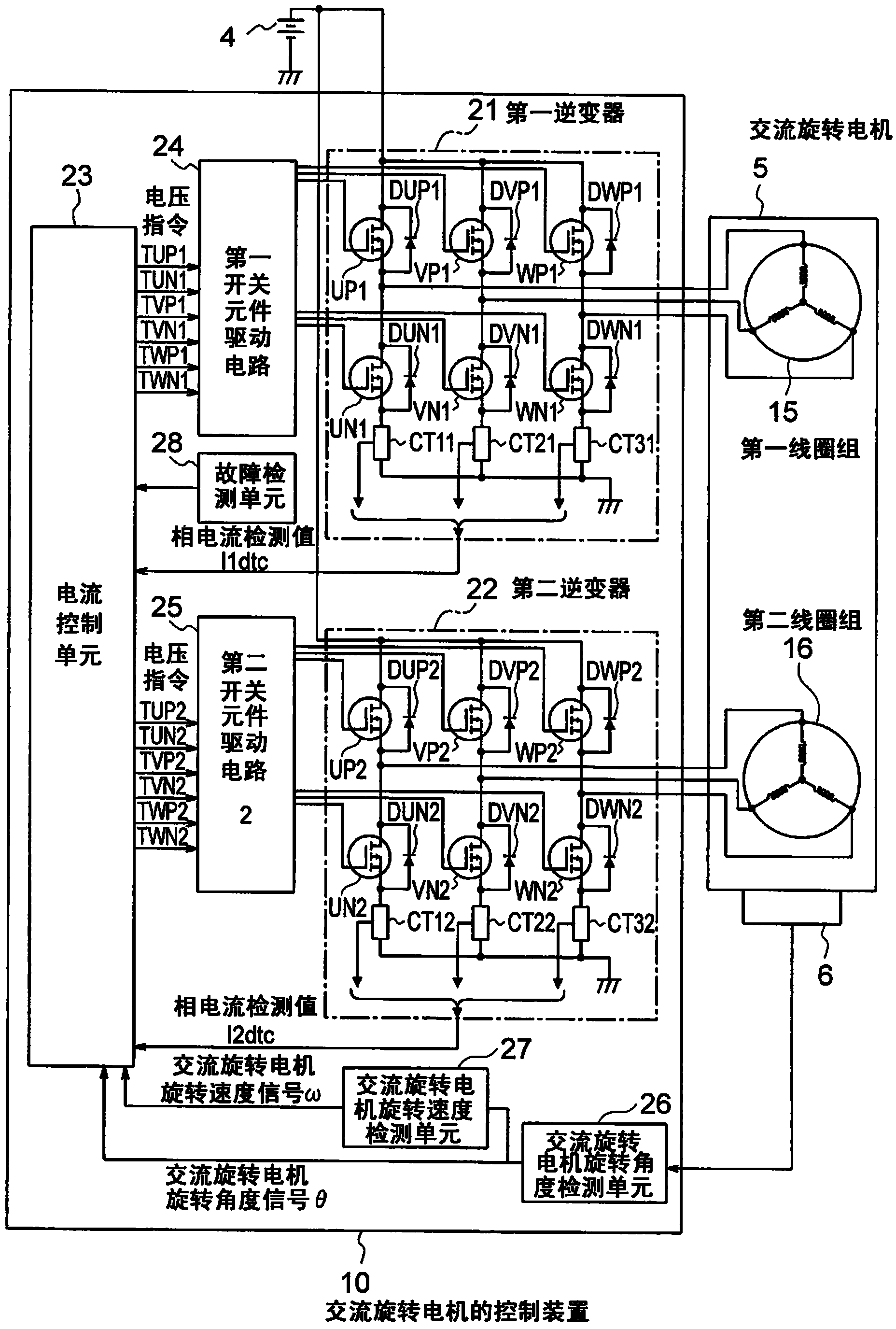
[0037] figure 1 It is a schematic block diagram showing an example of the overall configuration common to each embodiment of the control device for the AC rotating electric machine of the present invention. In addition, in addition to the control device 10 for the AC rotating electric machine, a power source 4, an AC rotating electric machine 5, and an AC rotating electric machine rotation angle sensor 6 that detects the rotation angle of the AC rotating electric machine 5 are also described.

[0038] The AC rotating electrical machine 5 includes a first coil group 15 composed of three phases: U1 phase, V1 phase, and W1 phase, and a second coil group 16 composed of three phases: U2 phase, V2 phase, and W2 phase. Each coil group is individually Combine phases with star connection. These multiple coil groups constitute a stator (not shown), and the AC rotating electric machine 5 is constituted by the stator, a rotor (not shown), and a rotating shaft fixed to the rotor. In addition...

Embodiment approach 2

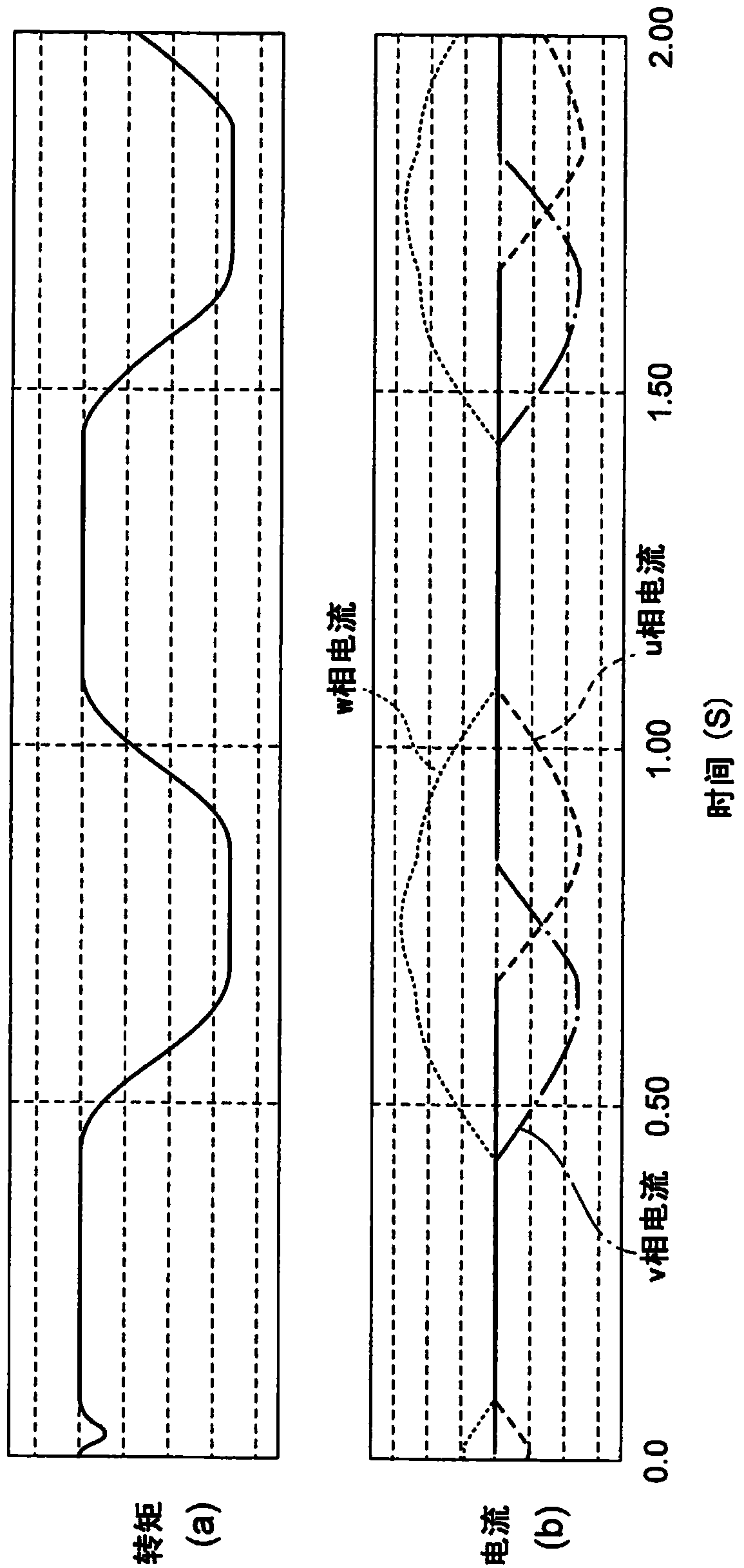
[0062] The overall structure of the control device of the AC rotating electrical machine in the second embodiment of the present invention is figure 1 the same. Taking a case where a short-circuit fault occurs on the low potential side of the W1 phase of the first coil drive system as an example, the operation of this embodiment will be described. Here, when both the first inverter 21 and the second inverter 22 are normal, the first coil group 15 and the second coil group 16 generate the same output torque.

[0063] At this time, the switching element WN1 located in the first inverter 21 is always in an on state. When switching elements other than WN1, namely UP1, UN1, VP1, VN1, and WP1 are turned off, an induced voltage will be generated in the first coil group 15. As a result, the first coil group 15 will flow Figure 7 (b) That kind of current. Figure 7 (a)(b) is a diagram showing the relationship between the elapsed time, torque and current when a short-circuit fault occurs ...

Embodiment approach 3

[0068] The overall structure of the control device of the AC rotating electric machine in the third embodiment of the present invention is figure 1 the same. The operation of this embodiment will be described by taking the case where an open fault occurs on the high potential side of the W1 phase of the first coil drive system as an example. Here, when both the first inverter 21 and the second inverter 22 are normal, the first coil group 15 and the second coil group 16 generate the same output torque.

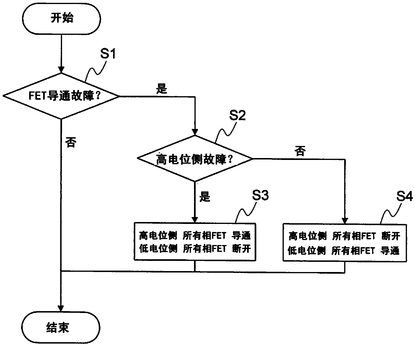
[0069] At this time, the switching element WP1 located in the first inverter 21 is always in the off state. When the switching elements other than WP1, that is, UP1, UN1, VP1, VN1, and WN1 are turned off, no current flows through the first coil group 15 and no braking torque is generated.

[0070] Figure 8 Shows the operation flowchart of the control of the current control unit 23. The current control unit 23 implements Figure 8 The control of the control flow shown produces a co...


PUM


Abstract

An AC rotary electrical machine and control device that controls an AC rotary machine is equipped with a plurality of sets of windings and comprises: a plurality of inverters having in each phase a switching element that controls the voltage applied to each phase of the aforementioned winding; current control means that controls the current flowing to the winding and that supplies a voltage instruction value corresponding to the aforementioned voltage to the aforementioned inverters; and fault detection means that detects malfunction representing at least either short-circuiting or open-circuiting of the aforementioned switching elements. The current control means sets the same-potential side of each phase of the malfunctioning inverter to the same condition as the fault, in accordance with the fault detected by the fault detection means, but continues to perform control of the inverter on the normal side i.e. the side which is not malfunctioning.

Description

Technical field [0001] The invention relates to control when a short-circuit fault or an open-circuit fault occurs in an AC rotating electric machine. Background technique [0002] For example, in the case of a control device using an AC rotating electric machine in an electric power steering or the like, when a failure occurs in a specific location, it is also desirable to continue driving the AC rotating electric machine while avoiding the failure. [0003] For example, the conventional AC rotating electrical machine control device described in the following Patent Document 1 includes a current control unit that determines the voltage of each phase based on the torque current command and the current flowing in each phase of the motor Instruction; switching element drive circuit, the switching element drive circuit instructs the inverter to switch operation based on each phase voltage instruction; inverter, the inverter receives the switching operation signal to drive the motor; c...

Claims


Application Information

Patent Timeline
Patent Type & Authority Applications(China)
IPC IPC(8): H02P6/12H02P21/00H02P21/05H02P21/22H02P23/04H02P23/07H02P23/16H02P27/06
CPCB62D5/0487B62D5/0403B62D5/046B62D5/0484B60L3/003B60L3/04B60L2220/56B60L2220/58B60L2240/423B60L2240/429B60L2240/526B60L2240/527H02P29/032H02P25/22Y02T10/64H02P6/12H02P6/14
Inventor 古川晃金原义彦冈田二郎
Owner MITSUBISHI ELECTRIC CORP
Why Eureka
Try Eureka