Wireless communication system and radio frequency device
A wireless communication system and wireless radio frequency technology, applied in the field of wireless communication systems and radio frequency devices, can solve problems such as low system reliability and inability of RRU to work, and achieve the effect of improving reliability
- Summary
- Abstract
- Description
- Claims
- Application Information
AI Technical Summary
Problems solved by technology
Method used
Image
Examples
Embodiment 1
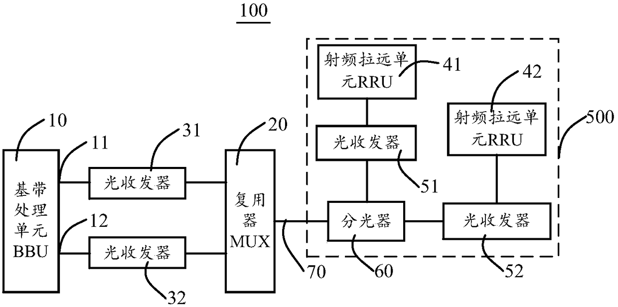
[0036] figure 1 A schematic structural diagram of a wireless communication system 100 provided by an embodiment of the present invention. Such as figure 1 As shown, the wireless communication system 100 includes: a baseband processing unit 10, an optical multiplexer 20, optical transceivers 31 and 32, and a wireless radio frequency device 500, and the wireless radio frequency device 500 includes radio remote units 41 and 42, optical transceivers 51 and 52 and beam splitter 60.
[0037] The baseband processing unit 10, referred to as BBU, is called Baseband Control Unit in full, and is also called a baseband control unit. The BBU 10 may include a transmission subsystem, a baseband subsystem, a control subsystem, and a power supply module. The transmission subsystem is used to realize the function of data transmission and reception, including the interface between the BBU and the core network / controller and the interface between the BBU and the radio frequency module. The i...
Embodiment 2
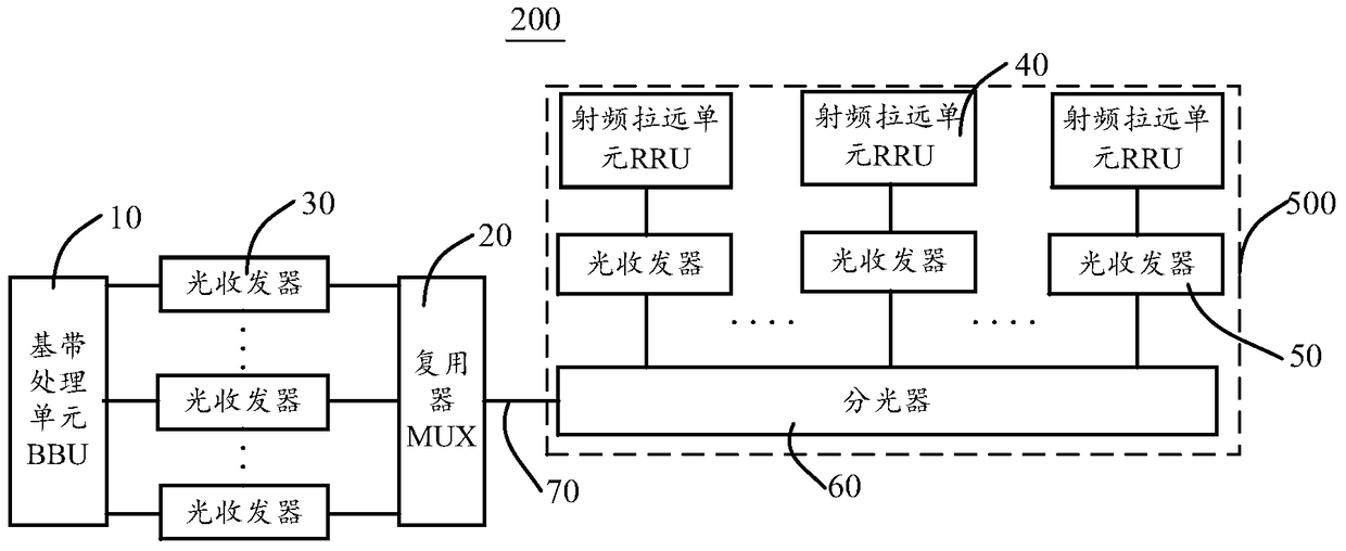
[0057] Based on the same inventive concept, the present application also provides a wireless communication system 200 . Such as figure 2 As shown, the difference between the wireless communication system 200 and the wireless communication system 100 lies in: the number of optical transceivers, the number of RRUs are different, and the optical splitters are different.
[0058] In this embodiment, the number of RRUs 40 is M. Correspondingly, M optical transceivers 50 are respectively connected to M RRUs 40, and M interfaces between the BBU 10 and M RRUs 40 are provided with M an optical transceiver 30. The optical splitter 60 may be a 1:N optical splitter, wherein M is an integer greater than or equal to 3, and N is an integer greater than or equal to 2. The M RRUs 40 are respectively connected to the optical splitter 60 through the M optical transceivers 50 .
[0059] In this embodiment, the N is equal to M, and the optical splitter 60 is a 1:M optical splitter with M+1 int...
Embodiment 3
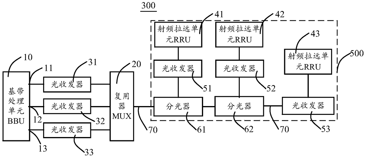
[0064] Based on the same inventive concept, the present application also provides a wireless communication system 300 . Such as image 3 As shown, it is a schematic structural diagram of a wireless communication system 300 provided by another embodiment of the present invention. The wireless communication system 300 and figure 1 The difference of the wireless communication system 100 in the above is that the number of optical splitters 60 is two, the number of RRU 40 is three, correspondingly, the number of interfaces of BBU 10 is also three, and the number of optical transceivers 30 connected to BBU 10 is The number of optical transceivers 50 connected to the RRU 40 is also three.
[0065] The number of optical splitters 60 is one less than the number of RRUs 40 , namely two optical transceivers 61 and 62 . Wherein, the optical splitter 61 is connected to the optical multiplexer 20 and the optical splitter 62, the RRU 41 is connected to the optical splitter 61 through the...
PUM
 Abstract
Description
Claims
Application Information
 - R&D
- Intellectual Property
- Life Sciences
- Materials
- Tech Scout
- Unparalleled Data Quality
- Higher Quality Content
- 60% Fewer Hallucinations
Browse by: Latest US Patents, China's latest patents, Technical Efficacy Thesaurus, Application Domain, Technology Topic, Popular Technical Reports.
© 2025 PatSnap. All rights reserved.Legal|Privacy policy|Modern Slavery Act Transparency Statement|Sitemap|About US| Contact US: help@patsnap.com


