Continuous reaction and regeneration technology used for conversion of methanol to gasoline through stationary bed adiabatic reactors

An adiabatic reactor, methanol conversion technology, which is applied in the petroleum industry, bulk chemical production, biological raw materials, etc., can solve the problem of "the remaining activity of the catalyst is difficult to use, etc., and achieve the improvement of the effective utilization rate, the reduction of energy consumption, and the reduction of raw material waste. Effect

Active Publication Date: 2014-11-12
SHANXI FEISHI TECH +2
View PDF5 Cites 10 Cited by
  • Summary
  • Abstract
  • Description
  • Claims
  • Application Information

AI Technical Summary

Problems solved by technology

[0021] The purpose of the present invention is to provide a continuous reaction and regeneration process of methanol conversion to gasoline in a fixed bed adiabatic reactor with simple operation and high catalyst reactivity utilization rate in the reaction process, so as to solve the existing technology of methanol conversion in a fixed bed adiabatic reactor to gasoline The problem that the existing catalyst "residual activity" is difficult to use, to achieve the purpose of improving catalyst activity and simplifying the operation method

Method used


Image

  • Continuous reaction and regeneration technology used for conversion of methanol to gasoline through stationary bed adiabatic reactors
  • Continuous reaction and regeneration technology used for conversion of methanol to gasoline through stationary bed adiabatic reactors

Examples


Embodiment 1

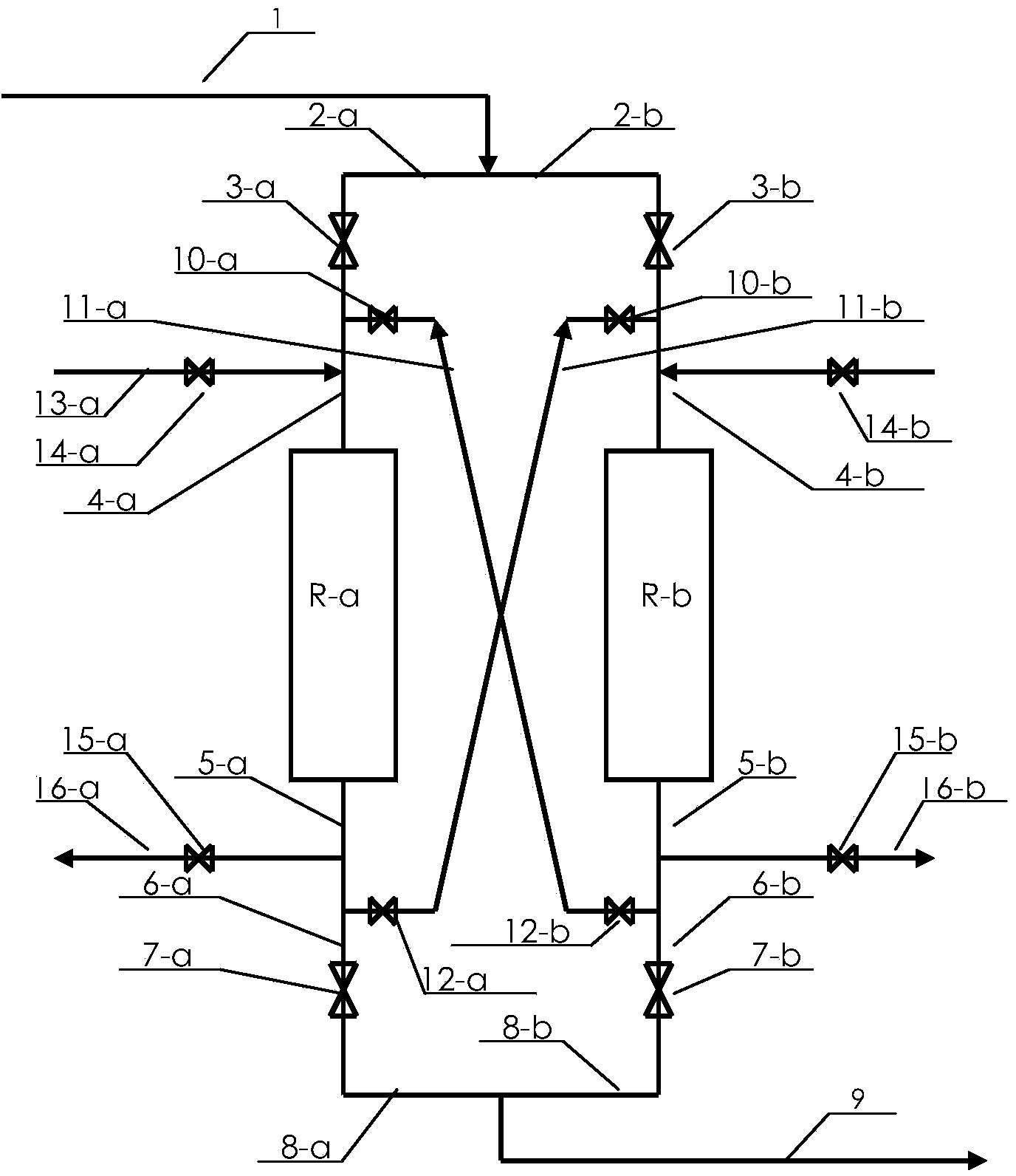
[0060] Two fixed-bed adiabatic reactors are attached by several pipes and valves. figure 1 Process connections shown.

[0061] R-a and R-b are fixed-bed adiabatic reactors made of stainless steel with an inner diameter of 3200 mm. The two reactors are respectively equipped with 23.29 tons of FeZrZSM-5 molecular sieve catalyst manufactured according to the method disclosed in Chinese Patent ZL200610012810.4, and the net height of the catalyst bed is 4830 mm. The total loading of FeZrZSM-5 molecular sieve catalyst in the two reactors is 46.58 tons.

[0062] The whole system was purged with nitrogen, and the oxygen content was confirmed to be less than 0.5%, and the system pressure was controlled at 1.8MPa.

[0063] Valves 3a, 7a are open and valves 3b, 7b, 10a, 10b, 12a, 12b, 14a, 14b, 15a, 15b are closed.

[0064] The system nitrogen circulation is established through the external circulation system, and the nitrogen flow rate entering the fixed-bed adiabatic reactor R-a thr...

Embodiment 2

[0102] The catalyst loading conditions and operating conditions are completely the same as those in Example 1, but the catalyst adopts ZSM-5 molecular sieve catalyst.

[0103] The main parameters of Example 2 are shown in Table 3.

[0104] The main technical indicators of Example 2 are shown in Table 4.

Embodiment 3

[0114] Same as Example 1, but the catalyst adopts ZSM-12 molecular sieve catalyst.

[0115] The main parameters of Example 3 are shown in Table 5.

[0116] The main technical indicators of Example 3 are shown in Table 6.

[0117] Table 5 Main parameters of Example 3

[0118] project

[0119] Table 6 Main technical indicators of embodiment 3

[0120] project

[0121] Number of reactors switched for regeneration per year


PUM


Abstract

Provided is a continuous reaction and regeneration technology used for conversion of methanol to gasoline through stationary bed adiabatic reactors. The two stationary bed adiabatic reactors work independently, the first reactor carries out a reaction for conversion of methanol to gasoline independently, and the second reactor is in a standby state; when catalysts in the first reactor approach to inactivation, the two reactors can work in a series connection mode through valve switchover until residual activity of the catalysts in the first reactor is fully utilized; the two reactors are made to work in a respective independent mode through valve switchover, the second reactor completes the reaction for conversion of methanol to gasoline independently, and the first reactor finishes catalyst regeneration operation independently and gets into the standby state. The technology is repeated in that way. The technology has the advantages that operation is simple, and the utilization rate of reactivity of the catalysts in the reaction process is high.

Description

technical field [0001] The invention belongs to the technology of converting methanol to gasoline. Specifically, it relates to a continuous reaction and regeneration process for converting methanol into gasoline in a fixed-bed adiabatic reactor. Background technique [0002] Mobil Corporation of the United States first discovered in the 1970s that methanol can be converted into hydrocarbon products under the catalysis of ZSM-5 molecular sieves. In September 1974, Mobil applied for the first patent of its MTG technology (USP3931349, Conversion of methanol to gasoline components). The new process of oil products provides a new way to synthesize high-octane gasoline from coal or natural gas. [0003] To date, a large body of literature has been written on processes and catalysts for methanol conversion to produce hydrocarbon products including gasoline components. From the perspective of reactor, the technology of methanol conversion to gasoline and other hydrocarbon product...

Claims


Application Information

Patent Timeline
Patent Type & Authority Applications(China)
IPC IPC(8): C10G3/00
CPCY02P20/52Y02P30/20
Inventor 李文怀张庆庚李晓崔晓曦潘国平范辉牛凤芹
Owner SHANXI FEISHI TECH
Why Eureka
Try Eureka