Reciprocating type shaft seal sealing performance testing method and device

A technology of sealing performance and testing method, which can be used in liquid/vacuum measurement for liquid tightness, by measuring the acceleration and deceleration rate of the fluid, and by detecting the appearance of the fluid at the leak point, etc., which can solve the detection hysteresis and pertinence. Not strong and other problems, to achieve the effect of accurate results, simple and convenient operation, accurate and reliable test results

Active Publication Date: 2014-11-12
菏泽建数智能科技有限公司
View PDF6 Cites 26 Cited by
  • Summary
  • Abstract
  • Description
  • Claims
  • Application Information

AI Technical Summary

Problems solved by technology

[0004] In order to overcome the shortcomings of the existing testing equipment for the sealing performance of reciprocating shaft seals such as hysteresis and lack of pertinence, the present invention provides a method that can conveniently detect various typical reciprocating shaft seals such as hydraulic seals and pneumatic seals. Test t

Method used


Image

  • Reciprocating type shaft seal sealing performance testing method and device
  • Reciprocating type shaft seal sealing performance testing method and device
  • Reciprocating type shaft seal sealing performance testing method and device

Examples


Embodiment 1

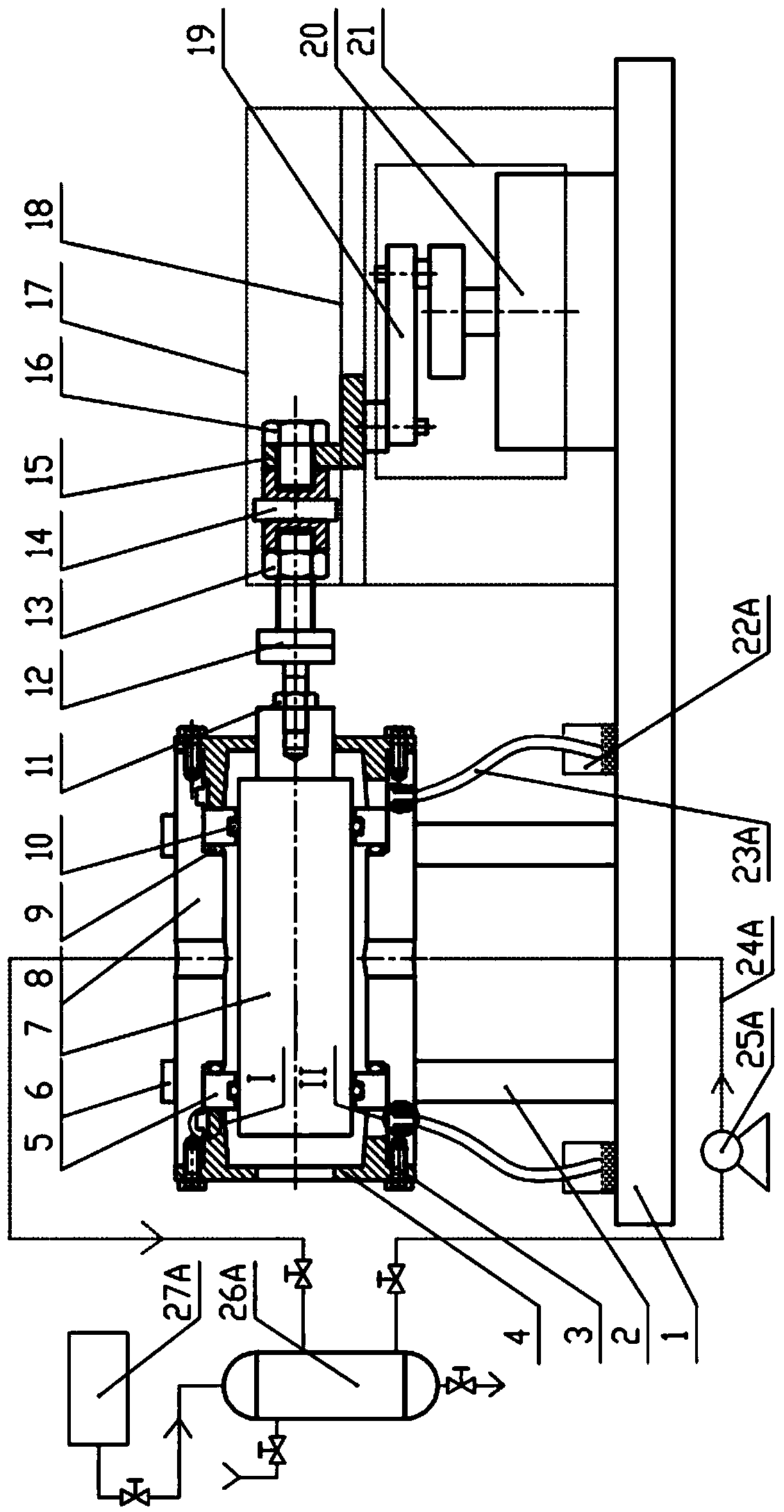
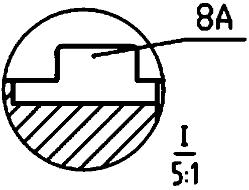
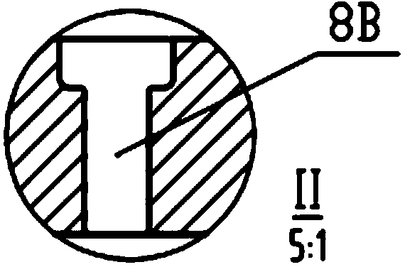
[0037] refer to Figure 1a , 1b , 1c, Figure 3a ~ Figure 3d , Figure 5a to Figure 6 , a test method for the sealing performance of a reciprocating shaft seal, said test method comprising the steps of:

[0038]a. Install the sealing ring 9 on the sealing ring installation ring 5 with a groove, the sealing ring installation ring 5 is installed in the outer cylinder 8 and compressed by the end caps 4 at both ends of the outer cylinder 8; install the sealing ring in the outer cylinder 8 The main shaft 7 connects the sealed main shaft 7 with the tension and pressure sensor 14 through the coupling 12, and the tension and pressure sensor 14 is connected with the support block 15; the support block 15 moves along the slide rail 18 on the support block bracket 17, and the power is reciprocated horizontally The device 21 provides;

[0039] b. The data acquisition and control system controls the auxiliary device and the reciprocating horizontal motion device 21, so that the space be...

Embodiment 2

[0050] refer to figure 2 , Figure 4a ~ Figure 4d , Figure 5a to Figure 6 The difference between this embodiment and Embodiment 1 is that this embodiment is aimed at the pneumatic sealing test, and the detection device includes a suction gun 26B, an air guide tube 23B and a helium mass spectrometer leak detector 22B, and the air guide tube 23B One end is connected to the helium mass spectrometer leak detector 22B, and the other end communicates with the first opening on the outer cylinder 8; the auxiliary device includes a gas conduit 24B, a pressure regulator 25B and a helium cylinder 27B, and the suction The gun 26B is arranged on the open end of the helium cylinder 27B, one end of the gas conduit 24B communicates with the second opening on the outer cylinder, and the other end is connected to the pressure regulator 25B, the pressure regulator The device 25B is connected to the suction gun 26B; the second opening on the outer cylinder opposite to the other end of the gas...


PUM


Abstract

The invention discloses a reciprocating type shaft seal sealing performance testing method and device. The device comprises a test bed frame, an outer cylinder, a sealing ring mounting loop for mounting of a sealing ring, a sealing main shaft, a pulling-pressing sensor, a supporting block, a reciprocating straight line moving device, an auxiliary device and a detecting device. The outer cylinder is fixedly arranged on the test bed frame through a support. The detecting device and the auxiliary device are connected with holes formed in the outer cylinder respectively. The sealing ring mounting loop is arranged in the outer cylinder. The two ends of the outer cylinder tightly press and seal the sealing ring mounting loop through end covers. The sealing main shaft is arranged in the outer cylinder and is connected with the pulling-pressing sensor through a coupler. The pulling-pressing sensor is connected with the supporting block which is connected with the reciprocating straight line moving device. The reciprocating straight line moving device, the pulling-pressing sensor and the auxiliary device are electrically connected with a data collecting control system.

Description

technical field [0001] The invention relates to a method and a device for testing the sealing performance of a reciprocating shaft seal, belonging to the field of fluid sealing technology research. Background technique [0002] Sealing technology has become an essential technology to ensure the long-term, safe and stable operation of modern industry. Generally speaking, seals can be divided into two categories: static seals between relatively static joints and dynamic seals between relatively moving joints. Reciprocating shaft seals are typical dynamic seals, widely used in internal combustion engines, hydraulic or pneumatic cylinders; reciprocating plunger pumps and compressors widely used in oil refining and petrochemical equipment use various piston seals and piston rod seals. The leakage of the sealing medium of the reciprocating shaft seal will not only cause huge economic losses, but also cause serious consequences such as environmental pollution, efficiency decline, ...

Claims


Application Information

Patent Timeline
IPC IPC(8): G01M3/26G01M3/20
Inventor 沈明学郑金鹏孟祥铠白少先彭旭东
Owner 菏泽建数智能科技有限公司
Why Eureka
Try Eureka