Bioreactor for efficiently and economically synchronously removing nitrate nitrogen and ammonia nitrogen

A bioreactor and economical technology, applied in the field of bioreactors for the simultaneous removal of nitrate nitrogen and ammonia nitrogen, can solve the problems of high energy consumption for oxygenation, low volumetric denitrification efficiency, and large floor area, and achieve the effect of optimizing the habitat

Active Publication Date: 2014-11-19
ZHEJIANG UNIV
View PDF6 Cites 13 Cited by
  • Summary
  • Abstract
  • Description
  • Claims
  • Application Information

AI Technical Summary

Problems solved by technology

The traditional biological denitrification method based on nitrification technology and denitrification technology has many defects, mainly including: ① Nitrification requires a large amount of oxygen, and the energy consumption of oxygenation is large; ② Denitrification requires a large amount of electron donors ( organic matter), high operating costs; ③The volumetric denitrification efficiency of the nitrification-denitrification process is low, resulting in a larger reaction tank volume and a larger floor area

Method used


Image

  • Bioreactor for efficiently and economically synchronously removing nitrate nitrogen and ammonia nitrogen
  • Bioreactor for efficiently and economically synchronously removing nitrate nitrogen and ammonia nitrogen

Examples


Embodiment Construction

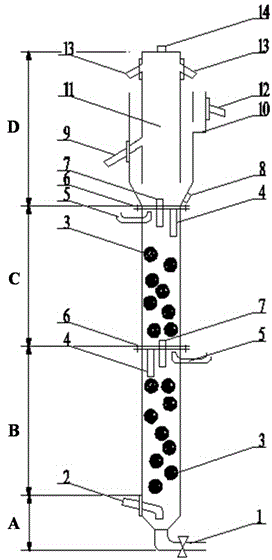
[0021] Such as figure 1 , 2 As shown, the efficient and economical bioreactor for simultaneous removal of nitrate nitrogen and ammonia nitrogen includes water distribution area A, short-range denitrification area B, anammox area C and separation area D from bottom to top; water distribution area A is from bottom to top There are sludge discharge pipe 1 and return-water inlet pipe 2 in sequence, the short-range denitrification zone B is directly connected to the top of the water distribution zone A, and a transverse partition is provided between the upper end of the short-range denitrification zone B and the bottom of the anammox zone C 6 and connected by a flange, another transverse partition 6 is provided between the upper end of the anammox zone C and the bottom of the separation zone D, and is connected by another flange, and mud guide pipes are respectively arranged on the two transverse partitions 6 4. The catheter 7, the upper part of the short-range denitrification zon...


PUM

PropertyMeasurementUnit
diameteraaaaaaaaaa
diameteraaaaaaaaaa
diameteraaaaaaaaaa

Abstract

The invention discloses a bioreactor for efficiently and economically synchronously removing nitrate nitrogen and ammonia nitrogen. A water distribution area, from bottom to top, is sequentially provided with a sludge discharge pipe and a water return-inlet pipe, a transverse partition plate is respectively arranged between the upper end of a short-range denitrification area and the bottom of an anaerobic ammonia oxidation area and between the upper end of the anaerobic ammonia oxidation area and the bottom of a separation area, the upper end of the short-range denitrification area and the bottom of the anaerobic ammonia oxidation area, as well as the upper end of the anaerobic ammonia oxidation area and the bottom of the separation area, are respectively connected through a flange, the two transverse partition plates are respectively provided with a sludge guide pipe and a liquid guide pipe, the upper part of the short-range denitrification area and the upper part of the anaerobic ammonia oxidation part are respectively provided with a gas pulse tube, the short-range denitrification area and the anaerobic ammonia oxidation area are respectively filled with a ball packing layer, the side wall of the separation area, from bottom to top, is sequentially provided with a sludge discharge outlet, an overflow tank and a water outlet, the center of the separation area is provided with a double-effect three-phase separator, the side wall of the middle part of the double-effect three-phase separator is provided with a return pipe, and the upper part of the double-effect three-phase separator is provided with a gas collecting connecting pipe and a gas exhaust pipe. According to the invention, an effect of simultaneous denitrification and carbon removal is achieved without aeration; due to the adoption of pulse exhaust, the floating loss of sludge is controlled; because the double-effect three-phase separator is provided, gas, liquid and solid phases are effectively separated.

Description

technical field [0001] The invention relates to a denitrification reactor. In particular, it relates to an efficient and economical bioreactor for synchronously removing nitrate nitrogen and ammonia nitrogen. Background technique [0002] After the nationwide implementation of "source control and emission reduction", the organic pollution of wastewater has been effectively treated, and nitrogen and phosphorus pollution has become a major environmental problem. According to the "National Environmental Statistical Bulletin", in 2012, the total discharge of wastewater in the country was 68.48 billion tons, the discharge of chemical oxygen demand (COD) was 24.237 million tons, and the discharge of ammonia nitrogen was 2.536 million tons. Lake "blooms" and offshore "red tides" frequently occur due to pollution, which have endangered agriculture, fishery, tourism and many other industries, and pose a serious threat to drinking water sanitation and food safety. Water pollution ha...

Claims


Application Information

Patent Timeline
Patent Type & Authority Applications(China)
IPC IPC(8): C02F3/28
Inventor 郑平厉巍林潇羽李晨旭张吉强
Owner ZHEJIANG UNIV
Why Eureka
Try Eureka