Unit for recovering thermal energy from exhaust gas of an internal combustion engine

A technology for internal combustion engines and exhaust gas recovery, applied in the direction of internal combustion piston engines, engine components, combustion engines, etc., can solve the problems of reducing the efficiency of the heat recovery process, and achieve the effect of simple structure

Active Publication Date: 2014-11-19
BOSAL EMISSION CONTROL SYST
View PDF8 Cites 8 Cited by
  • Summary
  • Abstract
  • Description
  • Claims
  • Application Information

AI Technical Summary

Problems solved by technology

Obviously in any location between the recovery position and the bypass position there may be a recirculation of exhaust gas which has been cooled after passing through the heat exchanger to a temperature which is substantially lower than that of the exhaust gas entering the system temperature, thus significantly reducing the efficiency of the heat recovery process

Method used


Image

  • Unit for recovering thermal energy from exhaust gas of an internal combustion engine
  • Unit for recovering thermal energy from exhaust gas of an internal combustion engine
  • Unit for recovering thermal energy from exhaust gas of an internal combustion engine

Examples


Embodiment Construction

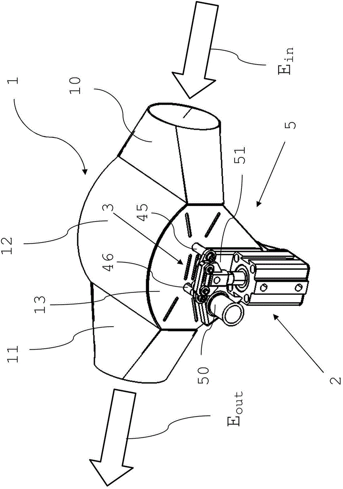
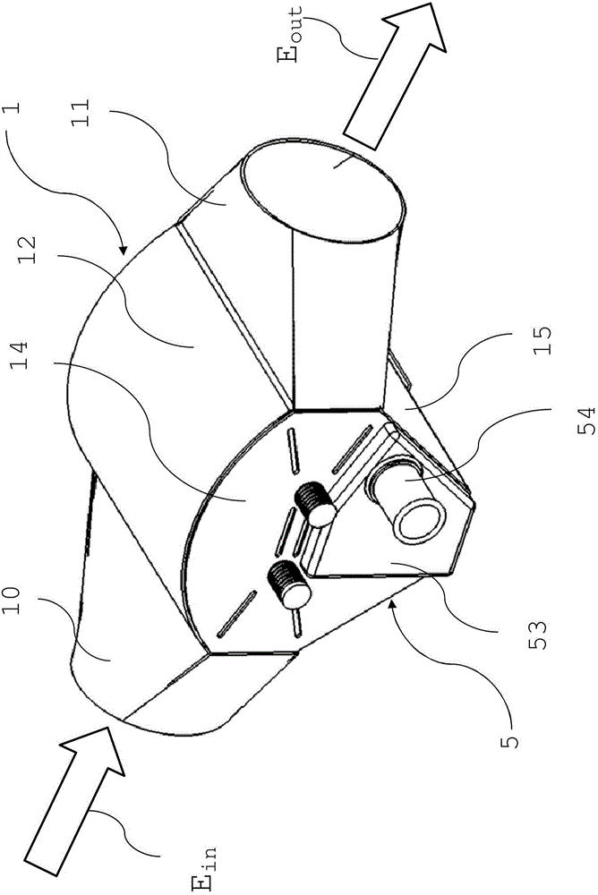
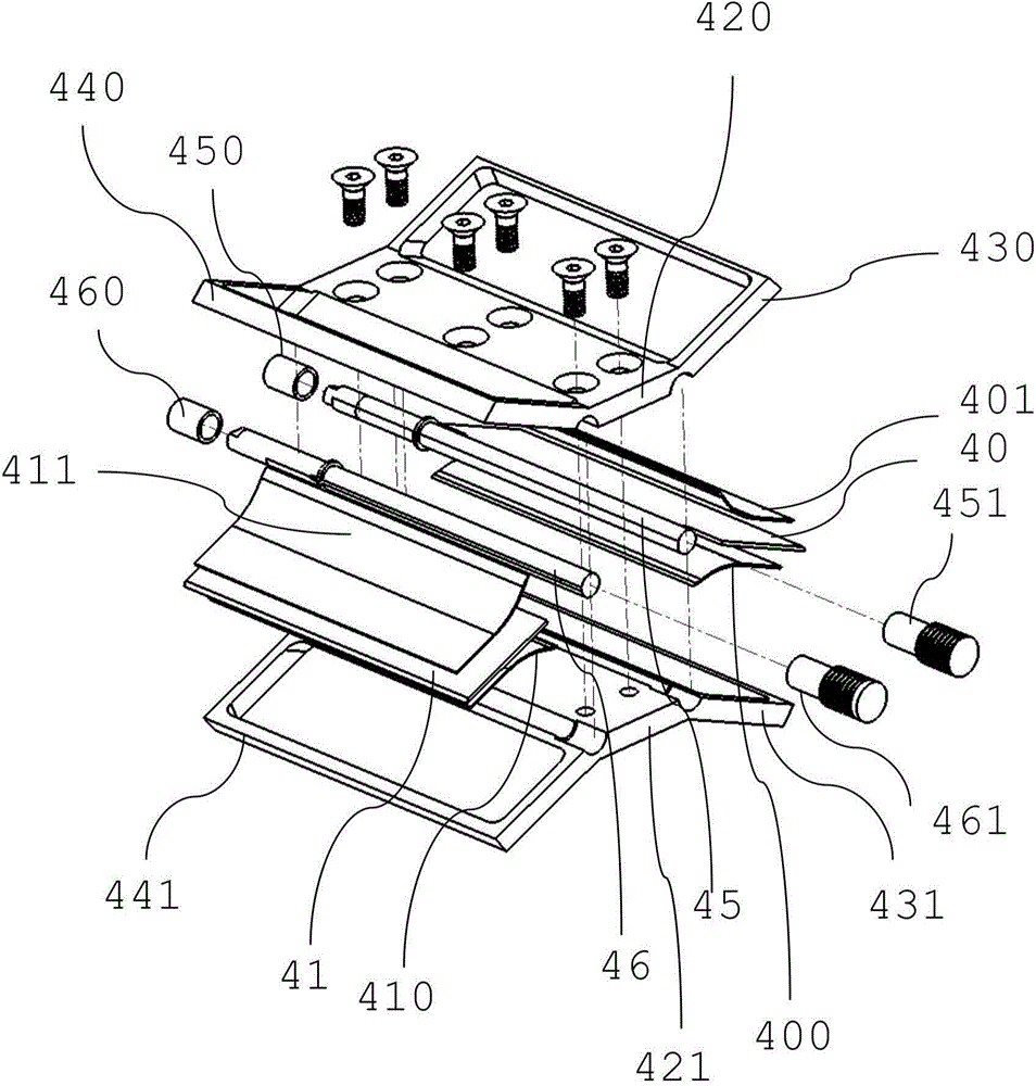
[0030] figure 1 and figure 2 are perspective views viewed from opposite sides (front view and rear view) of an embodiment of a thermal energy recovery unit according to the invention. As can be seen, the inflow exhaust gas Ein from the internal combustion engine or from a catalytic converter arranged downstream of the engine enters the thermal energy recovery unit via the inlet 10 of the housing 1 of the thermal energy recovery unit, flows through the thermal energy recovery unit, The thermal energy recovery unit then exits as outgoing exhaust gas Eout via outlet 11 of the housing. The housing 1 also includes a top wall 12 , two side walls 13 and 14 and a bottom 15 . as available from figure 1 It can be seen that the actuator 2 of the thermal energy recovery unit is coupled to the first shaft 45 of the first disc 40 by means of the mechanical linkage system 3 (see image 3 or Figure 4 ) and is coupled to the second shaft 46 of the second disc 41 (see image 3 or Figu...


PUM


Abstract

A unit for recovering thermal energy from exhaust gas of an internal combustion engine comprises: - an inlet (10); - an outlet (11); - a heat exchanger (5) arranged downstream of the inlet (10) and upstream of the outlet (11); and - a valve capable of being switched between a recovery position, in which the exhaust gas flows from the inlet (10) through the heat exchanger (5) to the outlet (11), and a bypass position, in which the exhaust gas flows from the inlet (10) through a bypass (8) to the outlet (11), wherein the valve comprises separate first (40) and second (41) valve bodies and associated separate first (430, 431) and second (440, 441) valve seats arranged upstream and downstream of the heat exchanger (5), respectively, and wherein the first (4) and second (41) valve bodies are adapted to be switched only simultaneously from the recovery position to the bypass position and vice versa.

Description

technical field [0001] The invention relates to a unit for recovering thermal energy. Background technique [0002] The automotive industry is increasingly focusing on reducing fuel consumption, pollutant emissions, recycling of materials, and recovery and conversion of otherwise dissipated heat energy in the design of engines, on-board systems, and vehicles themselves. [0003] With regard to the recovery and conversion of heat energy, the exhaust gases from internal combustion engines, after being treated by catalytic converters or even more complex treatment units, carry a certain amount of heat energy which can be recovered for various useful purposes. For example, it has been proposed to recover thermal energy from the exhaust for the following purposes: heating the cabin of the vehicle (by heating the engine's cooling water more rapidly); heating the lubricating oil more rapidly after a cold start of the engine to the optimum temperature (low viscosity); or to convert...

Claims


Application Information

Patent Timeline
Patent Type & Authority Applications(China)
IPC IPC(8): F01N5/02
CPCF02G5/02F01N2240/20F01N2240/02F01N2410/00F01N5/02F01N2240/36Y02T10/12
Inventor F·沃兰特斯J-P·H·汉森斯
Owner BOSAL EMISSION CONTROL SYST
Why Eureka
Try Eureka