Engine Phase Gear Adjust Torque Energy Saving Device

A phase gear, energy-saving device technology, applied in the direction of engine control, machine/engine, mechanical equipment, etc., can solve the problems of no air guide function, loss of suction volume, large power, etc., to solve the problem of low fuel power and mechanical efficiency. The effect of improving and saving energy

Inactive Publication Date: 2016-08-10
张鑫
View PDF6 Cites 0 Cited by
  • Summary
  • Abstract
  • Description
  • Claims
  • Application Information

AI Technical Summary

Problems solved by technology

[0002] like figure 1 Shown, the structure schematic diagram of all piston internal combustion engines such as existing aircraft, automobile, train, ship, power generation, machinery, motorcycle; When the angle K is 15°-0°, there is no torque when ignition is performed, and the torque is instantly lost by about 20%. At the same time, the crankshaft 59 needs to consume the original inertial power to rotate, and the torque of the crankshaft 58 and the crankshaft 59 gradually increases from small to large. , the piston mechanism moves to the bottom dead center as the torque to the crankshaft increases, the space of the combustion chamber 55 increases accordingly, and the torque of the crank 58 and the crankshaft 59 decreases accordingly. When the angle K between the piston connecting rod and the crank is At 90 degrees, the torque of the crank to the crankshaft is the largest, but at this time the torque is only about 25% of the initial work, and 50% of the torque is lost
The structure of the existing piston internal combustion engine causes a large amount of reactive power loss in power, wastes more than 70% of energy, and increases pollution emissions to the environment by more than 70%
[0003] Patent No. is the internal combustion engine disclosed by the patent of JP2009197737A, which is provided with two groups of pistons in the same cylinder. In a complete work process, one of the groups has two suction and exhaust processes, about 30% of the strokes are reversed, resulting in a loss of 30% of the suction volume, and when any valve is opened, it either hinders the piston. The space is either blocked on the suction and exhaust ports, or because the operating range of one piston oil ring and gas ring covers all the valve ports, the oil cannot be scraped back, or the combustion chamber at the top of the valve has no gas guiding function when it does work, and the gas cannot enter the two valves. The top of the piston works; 2. In the scheme of rotating speed 1:1, the ignition advance angle between the two sets of connecting rods and the crank is still between 15 degrees and 0 degrees, which is the same as the effect of the background technology. Moreover, when any valve is opened, Either the piston activity space is hindered, or the suction and exhaust ports are blocked, or because the operating range of one piston covers all the oil rings and gas rings, the oil cannot be scraped back, or the combustion chamber at the top of the valve has no air guiding function when doing work, and the gas cannot Enter the top of the two pistons to do work

Method used


Image

  • Engine Phase Gear Adjust Torque Energy Saving Device
  • Engine Phase Gear Adjust Torque Energy Saving Device
  • Engine Phase Gear Adjust Torque Energy Saving Device

Examples


Embodiment Construction

[0029] The specific implementation manner of the present invention will be described below in conjunction with the accompanying drawings.

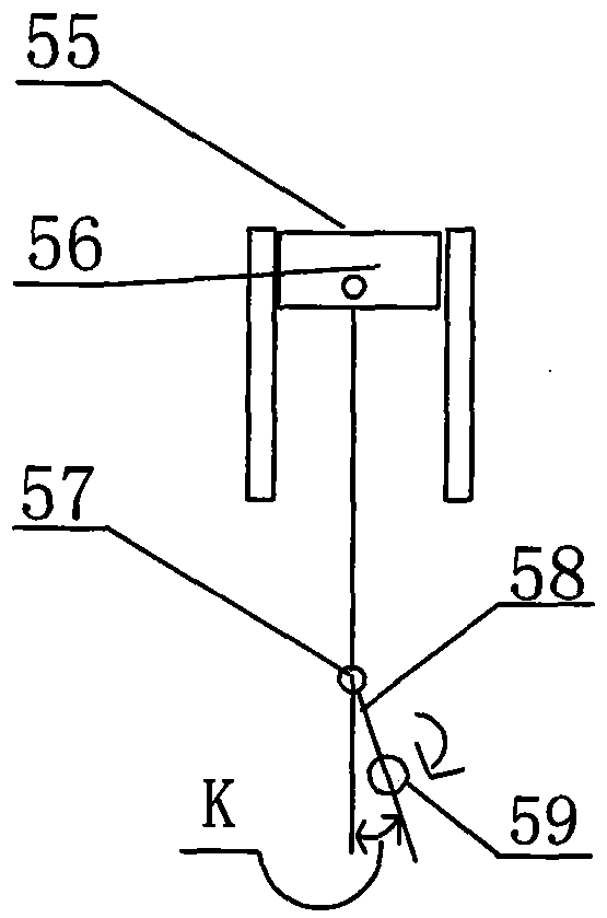
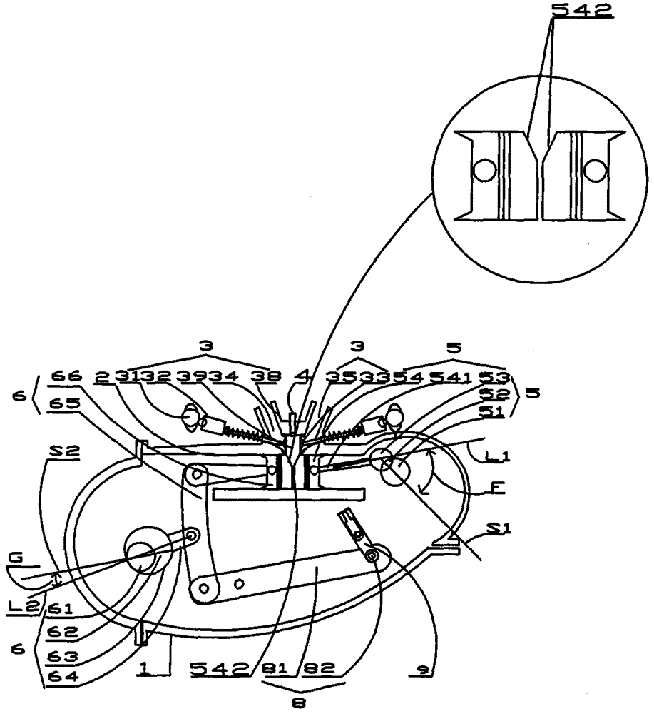
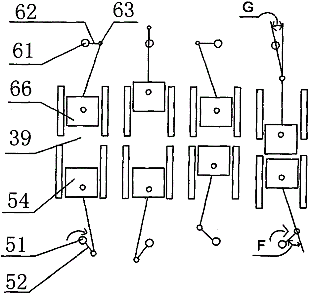
[0030] Such as Figure 2-Figure 4 Shown, a kind of engine phase gear is used to increase the torque energy-saving device, comprising body 1, cylinder 2, intake and exhaust valve mechanism 3, crankshaft air guide piston linkage 5, crankshaft air guide piston acceleration arm linkage 6, and The ignition mechanism 4, the ignition mechanism 4 can be a fuel nozzle or a spark plug or a fuel nozzle and a spark plug which are more commonly used at present, or compression ignition without ignition. The crankshaft gas pilot piston connecting rod mechanism 5 and the crankshaft gas pilot piston accelerating arm connecting rod mechanism 6 are respectively connected with the intermeshing phase gear 7 through shafts to ensure the crankshaft gas pilot piston connecting rod mechanism 5 and the crankshaft accelerating arm connecting rod mechanism 6 to opera...


PUM


Abstract

An apparatus for an engine to conserve energy by using phase gears to boost torque, comprising an engine body (1), a cylinder (2), an air intake / exhaust valve mechanism (3), a crankshaft gas piston connecting rod mechanism (5), a crankshaft gas piston accelerating arm connecting rod mechanism (6), and an ignition mechanism (4). The crankshaft gas piston connecting rod mechanism (5) and the crankshaft gas piston accelerating arm connecting rod mechanism (6) respectively are connected via shafts to phase gears (7) that are meshed with each other. This allows rotations of the crankshaft gas piston connecting mechanism (5) and the crankshaft accelerating arm connecting rod mechanism (6) to match correspondingly, while at the same time controls phase angles between crankshafts, thus allowing the crankshafts to work at a high torque and high efficiency state, giving full play to torque and power, thoroughly solving the problem of low power for engines running on low-calorific fuels, such as natural gas.

Description

technical field [0001] The invention relates to the field of engines, in particular to an energy-saving device for increasing the torque of a phase gear for an engine. Background technique [0002] Such as figure 1 Shown, the structure schematic diagram of all piston internal combustion engines such as existing aircraft, automobile, train, ship, power generation, machinery, motorcycle; When the angle K is 15°-0°, there is no torque when ignition is performed, and the torque is instantly lost by about 20%. At the same time, the crankshaft 59 needs to consume the original inertial power to rotate, and the torque of the crankshaft 58 and the crankshaft 59 gradually increases from small to large. , the piston mechanism moves to the bottom dead center as the torque to the crankshaft increases, the space of the combustion chamber 55 increases accordingly, and the torque of the crank 58 and the crankshaft 59 decreases accordingly. When the angle K between the piston connecting rod...

Claims


Application Information

Patent Timeline
Patent Type & Authority Patents(China)
IPC IPC(8): F02B75/28F02B75/32F02D13/02
CPCF02B75/28
Inventor 张鑫
Owner 张鑫
Why Eureka
Try Eureka