Method and system for dynamic measurement of liquid surface morphology and dosage of liquid propellant in storage tank

A technology for liquid and dynamic measurement of storage tanks, applied in the direction of measuring devices, instruments, etc., to achieve the effects of improving measurement accuracy and sensitivity, reducing equipment, and compact structure

Inactive Publication Date: 2014-11-19
BEIJING INSTITUTE OF TECHNOLOGYGY
View PDF11 Cites 7 Cited by
  • Summary
  • Abstract
  • Description
  • Claims
  • Application Information

AI Technical Summary

Problems solved by technology

[0006] The technical problem to be solved by this application is to provide a method and system for dynamic measurement of liquid propellant liquid level and dosage in a storage tank, so as to solve the problem that currently only one high-speed camera cannot be used without high-speed synchronization, and multiple cameras can be obtained. Directional liquid level and height information can be iteratively calculated in multiple directions to improve measurement accuracy and sensitivity; at the same time, the required equipment is reduced, making it possible to efficiently conduct full-field direct measurement of the dynamic deformation of the liquid surface without a reference surface

Method used


Image

  • Method and system for dynamic measurement of liquid surface morphology and dosage of liquid propellant in storage tank
  • Method and system for dynamic measurement of liquid surface morphology and dosage of liquid propellant in storage tank
  • Method and system for dynamic measurement of liquid surface morphology and dosage of liquid propellant in storage tank

Examples


Embodiment 1

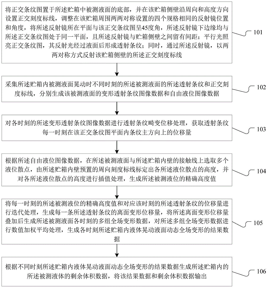
[0047] Such as figure 1 As shown, it is a process flow of a liquid propellant liquid surface profile and dosage dynamic measurement method for a storage tank described in Embodiment 1 of the present application.

[0048] Step 101, place the orthogonal fringe pattern at the bottom of the measured liquid level in the storage tank, and set orthogonal scale markings on the side wall of the storage tank along the circumferential and height directions, and arrange four specifications symmetrically around the storage tank. For the same reflector, adjust the position and angle of the reflector, the plane where the reflector is located is at an angle of 45 degrees to the orthogonal fringe pattern, the lower edge of the reflector is on the same plane as the orthogonal fringe pattern, and the There is a distance between the reflector and the side wall of the storage tank; the parallel light illuminates the orthogonal fringe pattern, and the reflected light forms transmission stripes afte...

Embodiment 2

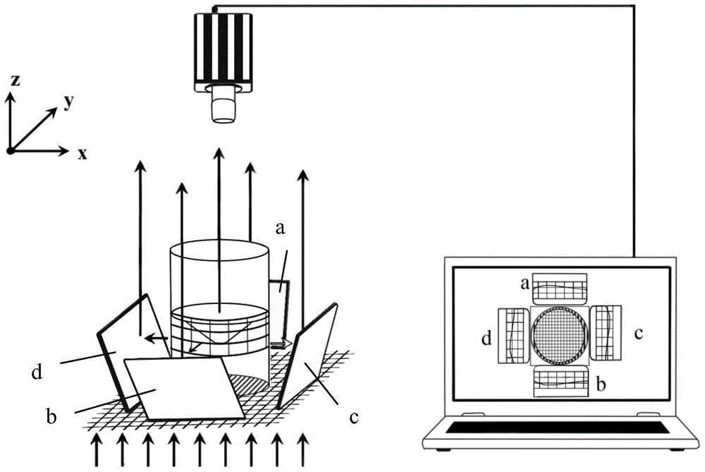
[0061] For the tank liquid propellant liquid surface morphology and dosage dynamic measurement method described in the first embodiment, it is necessary to set up a corresponding experimental system, such as figure 2 As shown, among them,

[0062] Precisely printed or drawn orthogonal scale markings with a certain interval along the circumferential and height directions on the side wall of the storage tank are used as position coordinate scales and height scales, and the storage tank contains translucent liquid to be measured. The orthogonal fringe pattern is printed or adhered (or placed) on the bottom of the tank, and the orthogonal fringe pattern can be set as a translucent fringe pattern with a specific frequency and size according to the needs of practical applications. A reflector group composed of four reflectors with the same specifications is arranged symmetrically around the storage tank, including: reflectors a, b, c, and d, wherein reflectors a and b are arranged ...

Embodiment 3

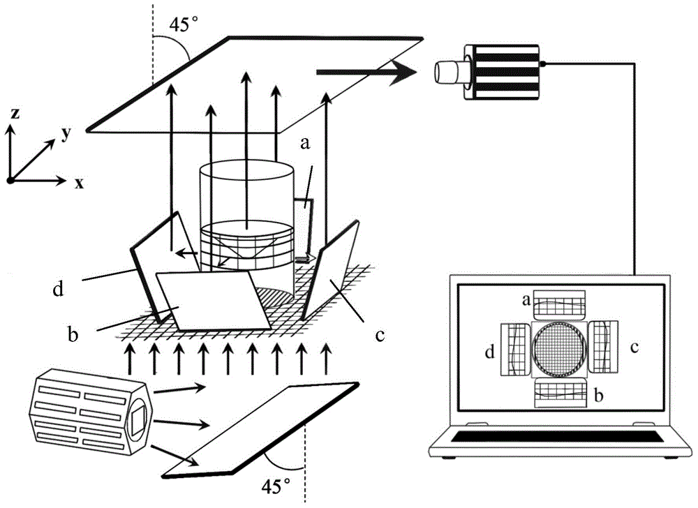
[0076] combine Figures 3 to 5 , the liquid propellant liquid surface morphology and dosage dynamic measurement method of the tank liquid propellant in this embodiment are specifically described:

[0077] The storage tank is an example of a cylindrical transparent flat-bottomed storage tank, and a storage tank with a square shape or other shapes with a horizontal bottom is also applicable.

[0078] The test system built is as follows:

[0079] Such as image 3 As shown, the orthogonal scale markings with a certain interval are accurately printed or drawn on the side wall of the tank along the circumferential direction and the height direction as the position coordinate scale and height scale. In order to realize the subsequent iterative calculation, the circumferential scale mark The whiskers are normal to the main direction of the stripes. The storage tank contains the translucent liquid to be tested. Design a semi-transparent orthogonal fringe pattern with specific frequ...


PUM

PropertyMeasurementUnit
Sensitivityaaaaaaaaaa

Abstract

The invention discloses a method and system for dynamic measurement of the liquid surface morphology and the dosage of liquid propellant in a storage tank. An orthogonal stripe pattern is arranged at the bottom of a measured liquid surface in the storage tank, orthogonal scale mark lines are arranged on the side wall of the storage tank, reflectors symmetrically arranged on the periphery of the storage tank are adjusted, transmission stripes and orthogonal scale mark lines are acquired when liquid waggles, and deformation transmission stripe image data and free liquid level image data are generated respectively; the displacement is acquired according to the deformation transmission stripe image data; the accurate height value of the liquid level is generated according to the free liquid level image data; according to the accurate height value and the displacement, the out-of-plane deformation displacement is generated, and then value weighted averaging is performed after multiple groups of whole deformation data are generated so that the result of changes of the whole liquid surface along with time can be obtained; residual volume data of measured liquid can be generated according to the whole deformation result data, and the result data and the residual volume data are output. According to the method and system, multi-directional liquid level height information, liquid surface morphology changes, residual volume and other parameters can be obtained just with one high speed camera.

Description

technical field [0001] The present application relates to the field of liquid slosh measurement, in particular to a method and system for dynamic measurement of liquid level profile and dose of liquid propellant in a storage tank. Background technique [0002] The study of liquid sloshing has always been an important research direction of dynamics and control and its interdisciplinary subjects. In terms of marine and ship dynamics, such as: oil and gas transportation, ship construction; in civil engineering and earthquake research, such as: high water towers, reservoirs, large dams; in earthquake response analysis and disaster protection research, vehicles and The sloshing problem of liquid storage tanks in transportation; and in the nuclear industry, biomedicine and other fields, the study of liquid sloshing is of great significance. Especially in the field of aerospace, modern spacecraft need to carry a large amount of liquid propellant in order to complete long-term and ...

Claims


Application Information

Patent Timeline
IPC IPC(8): G01D21/02
Inventor 刘战伟杨洋石文雄黄先富郭敬
Owner BEIJING INSTITUTE OF TECHNOLOGYGY
Why Eureka
Try Eureka