A large field of view curved surface focal plane imaging method and system based on image transmission fiber bundle

An imaging system and fiber optic bundle technology, applied in the direction of bundles of optical fibers, optics, optical components, etc., can solve the strict requirements of finished CCD detection and assembly debugging technology, complicated manufacturing process of curved surface CCD array, limited lens selection and combination, etc. , to achieve good application prospects, simplify design difficulty, reduce volume and weight

Active Publication Date: 2017-04-26
ACAD OF OPTO ELECTRONICS CHINESE ACAD OF SCI
View PDF4 Cites 0 Cited by
  • Summary
  • Abstract
  • Description
  • Claims
  • Application Information

AI Technical Summary

Problems solved by technology

However, the manufacturing process of the curved surface CCD array is very complicated, the cost is high, and it also puts forward strict requirements for the detection and assembly debugging technology of the finished CCD
In addition, the fixed surface shape also limits the choice and combination of lenses

Method used


Image

  • A large field of view curved surface focal plane imaging method and system based on image transmission fiber bundle
  • A large field of view curved surface focal plane imaging method and system based on image transmission fiber bundle
  • A large field of view curved surface focal plane imaging method and system based on image transmission fiber bundle

Examples


Embodiment 1

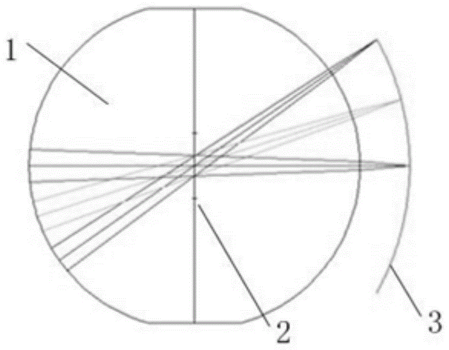
[0032] image 3 It is a flow chart of a large field of view curved surface focal plane imaging method based on an imaging fiber bundle provided in Embodiment 1 of the present invention. Such as figure 2 As shown, the method mainly includes the following steps:

[0033] Step 31, the incident light enters the Petzwan surface generated by the spherical lens through a spherical lens formed by cementing two groups of symmetrical lenses.

[0034] Step 32: After the light passes through the input end of the image transmission fiber bundle provided on the Petzwan surface, it is injected into the planar CCD array through the output end of the image transmission fiber bundle coupled to the planar charge-coupled device CCD array, Realize curved surface focal plane imaging.

[0035] Wherein, the input end of the image transmission fiber bundle can be arranged radially on the Petzwan surface; or, the input end of the image transmission fiber bundle is arranged on the Petzwan surface, a...

Embodiment 2

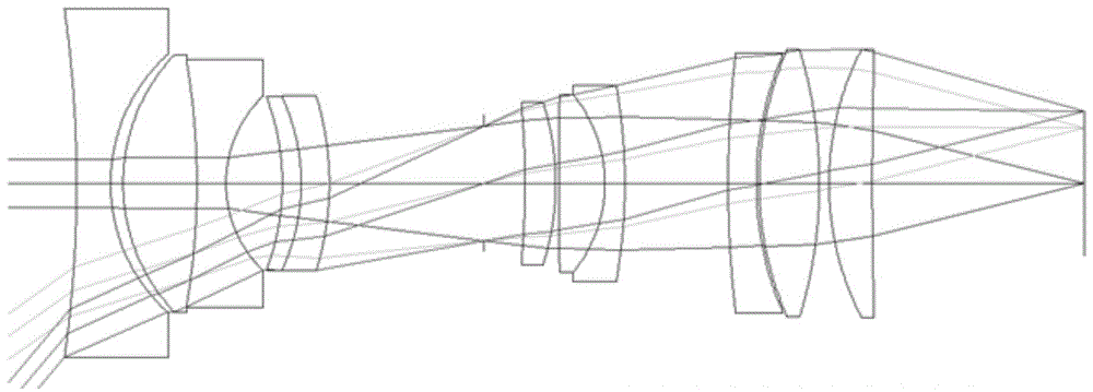
[0052] Figure 8 A schematic diagram of a large field of view curved focal plane imaging system based on an image-transmitting fiber bundle provided in Embodiment 2 of the present invention. Such as Figure 8 As shown, the system mainly includes:

[0053] The spherical lens 81 is formed by cementing two groups of symmetrical lenses;

[0054] The Petzwan surface 82 is produced by the spherical lens, and the incident light enters the Petzwan surface through the spherical lens;

[0055] The input end 83 of the image transmission fiber bundle is arranged on the Petzwan surface;

[0056] The output end 84 of the image transmission fiber bundle is coupled on the planar charge-coupled device CCD array 85;

[0057] After the light passes through the input end of the image transmission fiber bundle, it enters the planar CCD array through the output end of the image transmission fiber bundle to realize curved focal plane imaging.

[0058] Further, the image transmission fiber optic...


PUM


Abstract

The invention discloses a large-view-field curved surface focal plane imaging method and system based on an image transmitting optical fiber bundle. The method comprises the following steps: incident light is incident to a Pitts universal plane generated by a spherical lens through the spherical lens formed by gumming two groups of symmetrical lenses; and after the light passes through an image transmitting optical fiber bundle input end arranged on the Pitts universal plane, the light is incident to a planar charge coupled device (CCD) array through an image transmitting optical fiber bundle output end coupled to the planar CCD array so as to realize curved surface focal plane imaging. By adopting the method and system disclosed by the invention, the imaging effects of a large view field and high resolution are realized, and the cost of a large-view-field imaging system is greatly reduced.

Description

technical field [0001] The invention relates to the technical field of curved focal plane imaging, in particular to a large field of view curved focal plane imaging method and system based on an image transmission fiber bundle. Background technique [0002] The curved focal plane imaging technology is modeled on the retinal imaging mechanism (such as Figure 1a As shown), the entrance pupil rays converge on a curved focal plane array after passing through the spherical lens. Such as Figure 1b As shown, in the curved focal plane imaging system, the spherical lens 1 is equivalent to the lens, the diaphragm 2 is equivalent to the pupil, and the curved focal plane array is equivalent to the retina. The shape of the curved surface array matches the Petzwan surface 3 of the optical system, and is tangent to the Gaussian image plane of ideal imaging. The imaging system using the curved focal plane array can use the diaphragm at the center of the spherical lens to convert the inc...

Claims


Application Information

Patent Timeline
Patent Type & Authority Patents(China)
IPC IPC(8): G02B27/00G02B6/06
Inventor 相里斌袁艳柳青周锦松方煜
Owner ACAD OF OPTO ELECTRONICS CHINESE ACAD OF SCI
Why Eureka
Try Eureka