
Lower-iron-yoke shielding structure of transformer and manufacturing technology of lower-iron-yoke shielding structure of transformer

A technology of shielding structure and manufacturing process, applied in the direction of inductor/transformer/magnet manufacturing, magnetic field/electric field shielding, preventing/reducing unwanted electric/magnetic influences, etc. Partial discharge temperature, inability to play a shielding role, etc., to avoid damage or unreliable connection, excellent shielding performance, and stable shielding structure

Active Publication Date: 2014-11-19
CHINA XD ELECTRIC CO LTD
View PDF7 Cites 2 Cited by
  • Summary
  • Abstract
  • Description
  • Claims
  • Application Information

AI Technical Summary

Problems solved by technology

However, the existing shielding structure and processing methods have the following problems: 1) A complete shielding can only be formed by welding the aluminum foil paper and the tinned copper braided wire together, but because the melting points of the two are different, when welding: if the electric If the heating time of the soldering iron is too long, it is easy to burn out the aluminum foil shielding paper; if the heating time of the soldering iron is too short, the aluminum foil shielding paper and the tinned copper braided wire cannot be welded together. Structure prone to structural defects
2) Since the lower yoke shield is used at the lower end of the body, the lower yoke shield will also be under pressure when the body is compressed. If the aluminum foil shielding paper is cracked and cannot be repaired automatically, it will not be able to play a shielding role, causing overheating and partial discharge of the transformer Problems such as excessive temperature
Unable to meet the requirements for the use of lower yoke shielding

Method used


Image

  • Lower-iron-yoke shielding structure of transformer and manufacturing technology of lower-iron-yoke shielding structure of transformer

Examples


Embodiment Construction

[0027] The present invention is described in further detail below in conjunction with accompanying drawing:

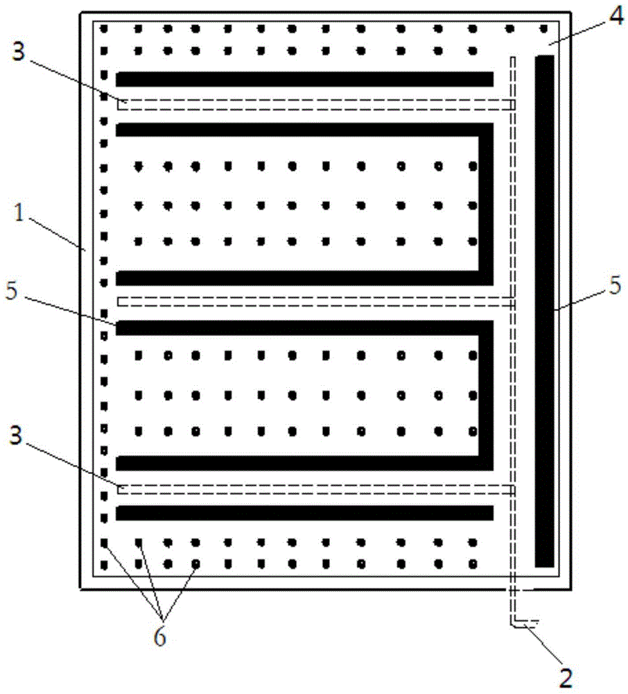
[0028] A lower iron yoke shielding structure of a transformer in the present invention, such as figure 1 As shown, it includes insulating paperboard 1, laying lead-out wire 2 and shielding wire 3 bonded on insulating paperboard 1, and wrinkled carbon black conductive paper 4; lead-out wire 2 and shielding wire 3 are connected, and wrinkle carbon black conductive paper 4 passes through The bonding structure arranged on the outside of the lead wire 2 and the shielding wire 3 is bonded and fixed to the insulating cardboard.

[0029] Among them, the lead-out wires 2 are vertically connected with several mutually parallel shielded wires 3 respectively; the lead-out wires 2 are made of copper braid, and the ends of the copper braid are provided with soldering heads; the shielded wires 3 are made of copper tape, and the lead-out wires 2 and the shielded wire 3 are fixed by s...


PUM


Abstract

The invention discloses a lower-iron-yoke shielding structure of a transformer. The lower-iron-yoke shielding structure comprises an insulating cardboard, a leading-out wire, shielding wires and wrinkled carbon-black conductive paper, wherein the leading-out wire and the shielding wires are laid on and spliced to the insulating cardboard. The leading-out wire is connected with the shielding wires. The wrinkled carbon-black conductive paper is fixedly spliced with the insulating cardboard through a splicing structure arranged on the outer sides of the leading-out wire and the shielding wires. A manufacturing technology of the lower-iron-yoke shielding structure of the transformer includes the following steps: (1) copper strips are perpendicularly welded to one sides of copper braided wires respectively through tin soldering; (2) the copper strips and the copper braided wires which are well welded are spliced to the insulating cardboard, and the leading-out ends of the copper braided wires are arranged to extend out of the range of the insulating cardboard; (3) the copper strips and the copper braided wires are covered with the wrinkled carbon-black conductive paper, and the wrinkled carbon-black conductive paper is spliced with the insulating cardboard. According to the lower-iron-yoke shielding structure and the manufacturing technology, the leading-out wire and the shielding wires are respectively spliced with the insulating cardboard, and the insulating cardboard is spliced with the wrinkled carbon-black conductive paper, so that electrical connection between the parts is guaranteed, structure ductility is good, and reliability is high.

Description

technical field [0001] The invention relates to the technical field of transformer manufacturing, in particular to a lower iron yoke shielding structure of a transformer and a manufacturing process thereof. Background technique [0002] The lower iron yoke shield used in existing transformer products is made of aluminum foil paper as the shielding material, which is made by bonding a plurality of metal aluminum foil films on very thin insulating paper. Bond the aluminum foil paper to the insulating cardboard, then place the lead wire made of tinned copper braided wire on the aluminum foil paper, and finally pass the solder potion or solder liquid and use an electric soldering iron to connect the aluminum foil paper and the tinned copper braided wire The wires are welded together by solder joints to make reliable contact to form a shielding structure. However, the existing shielding structure and processing methods have the following problems: 1) A complete shielding can onl...

Claims


Application Information

Patent Timeline
Patent Type & Authority Applications(China)
IPC IPC(8): H01F27/36H01F41/00H05K9/00
Inventor 田子九张伟红邓颖董春雷马晓娟
Owner CHINA XD ELECTRIC CO LTD
Learn More