MCOB LED package structure

A packaging structure, LED chip technology, applied in the direction of electrical components, electrical solid devices, circuits, etc., can solve the problems of failure, heat can not be quickly transferred to the heat sink of lamps, heat cannot be quickly separated and other problems

Inactive Publication Date: 2014-11-19
DONGGUAN INST OF OPTO ELECTRONICS PEKING UNIV
View PDF4 Cites 6 Cited by
  • Summary
  • Abstract
  • Description
  • Claims
  • Application Information

AI Technical Summary

Problems solved by technology

The heat of the LED chip is affected by the heat dissipation channels such as the LED light source substrate, and the heat cannot be quickly transferred to the heat sink and the outside of the lamp, resulting in an increase in thermal resistance.
Moreover, the place where the LED chips gather will produce a heat island effect, and the heat cannot be separated quickly
The above problems cause the LED light source to fail due to overheating when working for a long time

Method used


Image

  • MCOB LED package structure
  • MCOB LED package structure
  • MCOB LED package structure

Examples


Embodiment Construction

[0020] In order to further understand the features, technical means, specific objectives and functions achieved by the present invention, and to analyze the advantages and spirit of the present invention, a further understanding of the present invention can be obtained through the following detailed description of the present invention in conjunction with the accompanying drawings and specific embodiments.

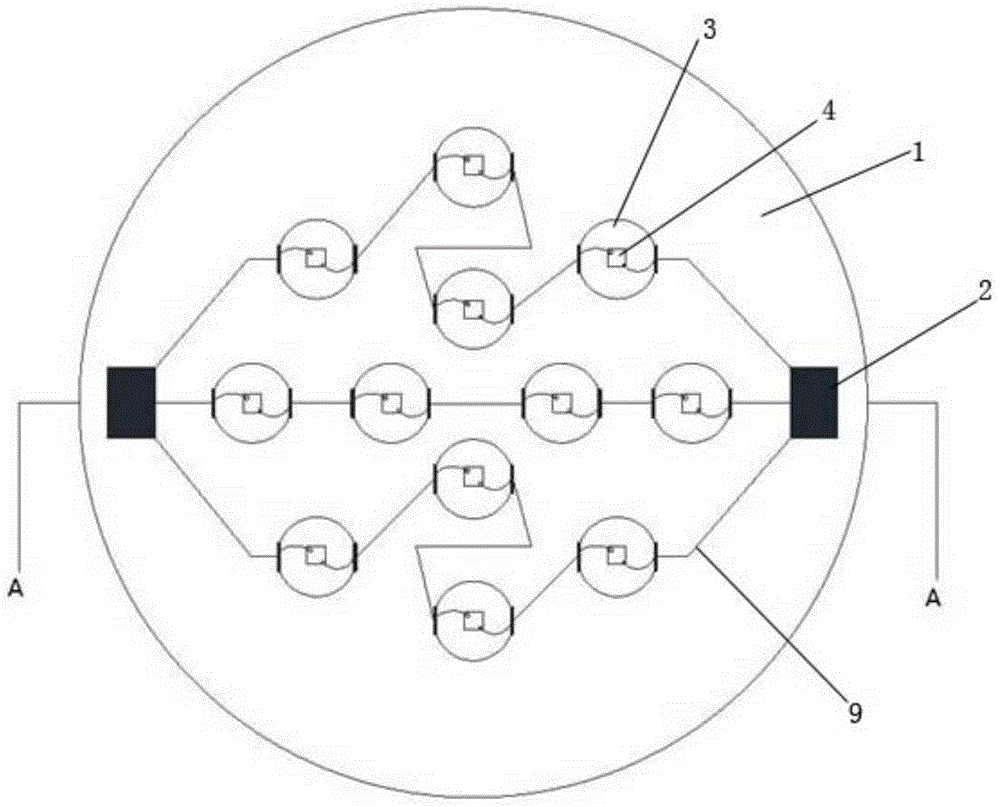
[0021] See attached figure 1 , which are schematic structural diagrams of an MCOB LED packaging structure according to an embodiment of the present invention.

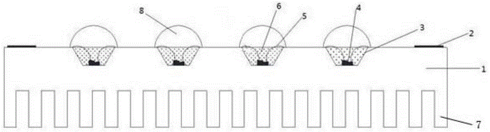
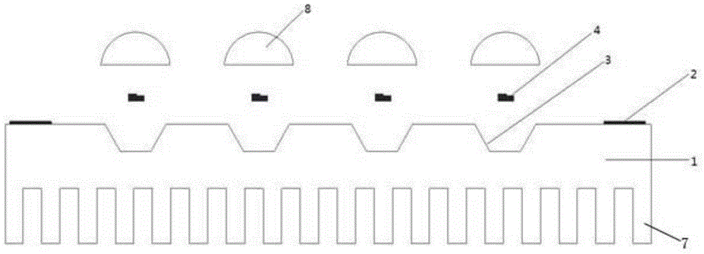
[0022] The MCOB LED packaging structure includes a substrate 1 and twelve LED chips 4 . The base plate 1 adopts a metal material with high thermal conductivity and is integrally formed. In other embodiments, the base plate 1 can also be made of ceramic material or polymer composite material with high thermal conductivity.

[0023] The substrate 1 includes a first surface and a second surface opposite to the first ...


PUM


Abstract

An MCOB LED package structure comprises a substrate and a plurality of LED chips. The substrate comprises a first surface and a second surface back onto the first surface, a plurality of cup-shaped bowls are formed in the first surface, and the second surface is provided with a plurality of cooling fins. The substrate is of a structure integrally formed by metal materials or ceramic materials or polymer composite materials. The cup-shaped bowls are manufactured through optical simulation. The LED chips are fixed into the cup-shaped bowls, the first surface is provided with an electronic circuit and a plurality of different power interfaces, the LED chips are connected with the electronic circuit, and the electronic circuit is connected with the power interfaces. According to the MCOB LED package structure, the substrate of the structure integrally formed by the metal materials or the ceramic materials or the polymer composite materials is adopted, so that thermal transmission capacity of the substrate is increased; the cup-shaped bowls are directly formed in the substrate, and the LED chips are installed in the cup-shaped bowls, so that the heat transmission distance is shortened; the cooling fins are arranged, the cooling rate is further increased, and therefore the cooling effect of the LED package structure is improved.

Description

technical field [0001] The invention relates to the application field of LED light source packaging technology, in particular to an MCOB LED packaging structure. Background technique [0002] Traditional LED (Light Emitting Diode, light emitting diode, abbreviated as LED) light sources are mostly fixed on the heat sink of the LED lamp through surface mount technology (Surface Mount Technology, abbreviated as SMT). When the LED chip emits light, the heat is affected by the heat dissipation channels such as the LED light source substrate, and the heat cannot be quickly transferred to the heat sink and the outside of the lamp, resulting in an increase in thermal resistance. Moreover, the place where the LED chips gather will produce a heat island effect, and the heat cannot be separated quickly. The above-mentioned problems cause the LED light source to easily fail due to overheating when it works for a long time. Contents of the invention [0003] Based on this, an MCOB (M...

Claims


Application Information

Patent Timeline
Patent Type & Authority Applications(China)
IPC IPC(8): H01L25/075H01L33/48H01L33/62H01L33/50H01L33/64
Inventor 郑小平童玉珍刘南柳
Owner DONGGUAN INST OF OPTO ELECTRONICS PEKING UNIV
Why Eureka
Try Eureka