High voltage direct current circuit breaker topology circuit

A topological circuit and high-voltage direct current technology, applied in the direction of direct current network circuit devices, circuit devices, electrical components, etc., can solve the problems of poor economy, large loss, and breaking time that cannot meet the multi-terminal flexible direct current transmission system, etc., and achieve low equipment cost, The effect of prolonging the service life and novel structure

Active Publication Date: 2014-11-19
STATE GRID CORP OF CHINA +2
View PDF3 Cites 23 Cited by
  • Summary
  • Abstract
  • Description
  • Claims
  • Application Information

AI Technical Summary

Problems solved by technology

[0003] There are usually three ways to break the DC current. One is to add an auxiliary circuit on the basis of the conventional AC mechanical circuit breaker to superimpose the increased oscillation current on the DC current of the breaking arc gap, and use the current to break when the current crosses zero. The mechanical circuit breaker manufactured using this principle cannot meet the requirements of the multi-terminal flexible DC transmission system in terms of breaking time; one is to use high power to turn off power electronic devices and directly break the DC current, using this principle Although the manufactured solid-state circuit breaker can meet the requirements of the multi-terminal flexible DC system in terms of time, the loss is too large during normal conduction, and the economy is poor; the last one is a combination of mechanical switches and power electronic devices. In normal operation, the mechanical switch conducts the current, and when the fault occurs, the current of the main branch is transferred to the branch of the power electronic device connected in parallel, and then the power electronic device breaks the current

Method used


Image

  • High voltage direct current circuit breaker topology circuit
  • High voltage direct current circuit breaker topology circuit
  • High voltage direct current circuit breaker topology circuit

Examples


Embodiment 1

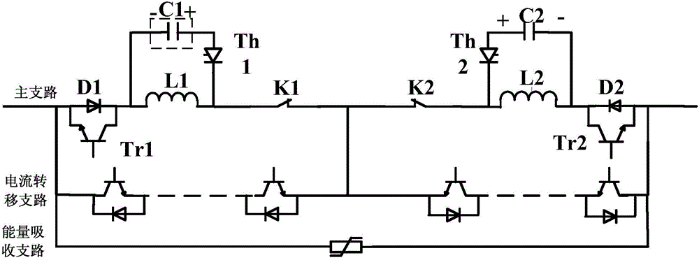
[0030] Such as figure 1 , the topological circuit of the high-voltage DC circuit breaker includes a main branch, a current transfer branch and an energy absorption branch; the main branch, the current transfer branch and the energy absorption branch are connected in parallel.

[0031] 1) The main branch circuit includes a first main branch circuit and a second main branch circuit connected in series; the first main branch circuit includes a fast mechanical switch K1, an LC discharge circuit and power electronic devices;

[0032] The power electronic device uses a transistor Tr1 with an anti-parallel diode. The LC discharge circuit includes an inductor L1, a capacitor C1 and a thyristor Th1. One end of the inductor L1 is connected to the cathode of the anti-parallel diode D1, and the other end is connected to a fast mechanical switch K1, capacitor C1 and thyristor Th1. After being connected in series, it is connected in parallel at both ends of the inductor L1;

[0033] The se...

Embodiment 2

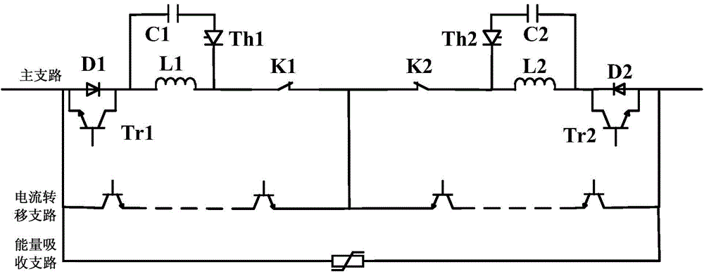
[0044] Such as figure 2 , the topological circuit of the high-voltage DC circuit breaker includes a main branch, a current transfer branch and an energy absorption branch; the main branch, the current transfer branch and the energy absorption branch are connected in parallel.

[0045] 1) The main branch circuit includes a first main branch circuit and a second main branch circuit connected in series; the first main branch circuit includes a fast mechanical switch K1, an LC discharge circuit and power electronic devices;

[0046] The power electronic device uses a transistor Tr1 with an anti-parallel diode. The LC discharge circuit includes an inductor L1, a capacitor C1 and a thyristor. One end of the inductor L1 is connected to the cathode of the anti-parallel diode D1, and the other end is connected to a fast mechanical switch K1. The capacitor C1 is connected in series with the thyristor Th1. Afterwards, it is connected in parallel at both ends of the inductor L1;

[0047...

Embodiment 3

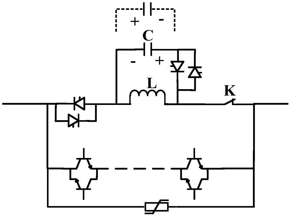
[0052] Such as image 3 , the topological circuit of the high-voltage DC circuit breaker includes a main branch, a current transfer branch and an energy absorption branch; the main branch, the current transfer branch and the energy absorption branch are connected in parallel.

[0053] 1) The main branch includes fast mechanical switch K, LC discharge circuit and power electronic devices; the inherent oscillation period of LC discharge circuit T = 2 π LC ;

[0054] The power electronic device adopts two thyristor anti-parallel structure; LC discharge circuit includes inductor L, capacitor C and two thyristor anti-parallel structure, one end of inductor L1 is connected to two thyristor anti-parallel structure, the other end is connected to fast mechanical switch K, capacitor C and Two thyristor anti-parallel structures are connected in parallel at both ends of the inductor L after being connected ...


PUM


Abstract

The invention provides a high voltage direct current circuit breaker topology circuit which comprises a main branch, a current transfer branch and an energy absorption branch. The main branch, the current transfer branch and the energy absorption branch are connected in parallel. According to the high voltage direct current circuit breaker topology circuit provided by the invention, the structure of a circuit topology is simple; a stable current zero crossing point is in a breaking process; and the high voltage direct current circuit breaker topology circuit has the advantages of convenient control, flexible application, easy realization, high current breaking capacity, high withstand voltage level, high expansibility and low equipment cost.

Description

technical field [0001] The invention relates to a topological circuit, in particular to a high-voltage direct current circuit breaker topological circuit. Background technique [0002] With the application of multi-terminal flexible DC and DC grid technology based on voltage source converter (VSC), fast DC circuit breakers have become one of the key equipment to ensure the stable, safe and reliable operation of the system. In the AC system, the AC current has two natural zero-crossing points in one cycle, and the AC circuit breaker uses the natural zero-crossing points of the current to cut off the current, while in the DC system, the DC current does not have a natural zero-crossing point, so the DC current The breaking of the current is much more difficult than the breaking of the alternating current. [0003] There are usually three ways to break the DC current. One is to add an auxiliary circuit on the basis of the conventional AC mechanical circuit breaker to superimpos...

Claims


Application Information

Patent Timeline
Patent Type & Authority Applications(China)
IPC IPC(8): H02J1/00
Inventor 高阳魏晓光高冲贺之渊周万迪
Owner STATE GRID CORP OF CHINA
Why Eureka
Try Eureka