Rotor temperature monitoring method for permanent magnet synchronous motor and system therefor

A permanent magnet synchronous motor, rotor temperature technology, applied in the temperature measurement of moving solids, synchronous machines, thermometers with directly sensitive electrical/magnetic components, etc., can solve problems such as low system reliability

Active Publication Date: 2014-11-19
CSR ZHUZHOU ELECTRIC LOCOMOTIVE RES INST
View PDF3 Cites 23 Cited by
  • Summary
  • Abstract
  • Description
  • Claims
  • Application Information

AI Technical Summary

Problems solved by technology

[0005] In view of this, the present application provides a rotor temperature monitoring method of a permanent magnet synchronous motor, which is used to monitor the rotor temperature of a permanent magnet synchronous motor, so as to avoid the system reliability caused by configuring a temperature sensor to monitor the temperature of the motor rotor low problem

Method used


Image

  • Rotor temperature monitoring method for permanent magnet synchronous motor and system therefor
  • Rotor temperature monitoring method for permanent magnet synchronous motor and system therefor
  • Rotor temperature monitoring method for permanent magnet synchronous motor and system therefor

Examples


Embodiment 1

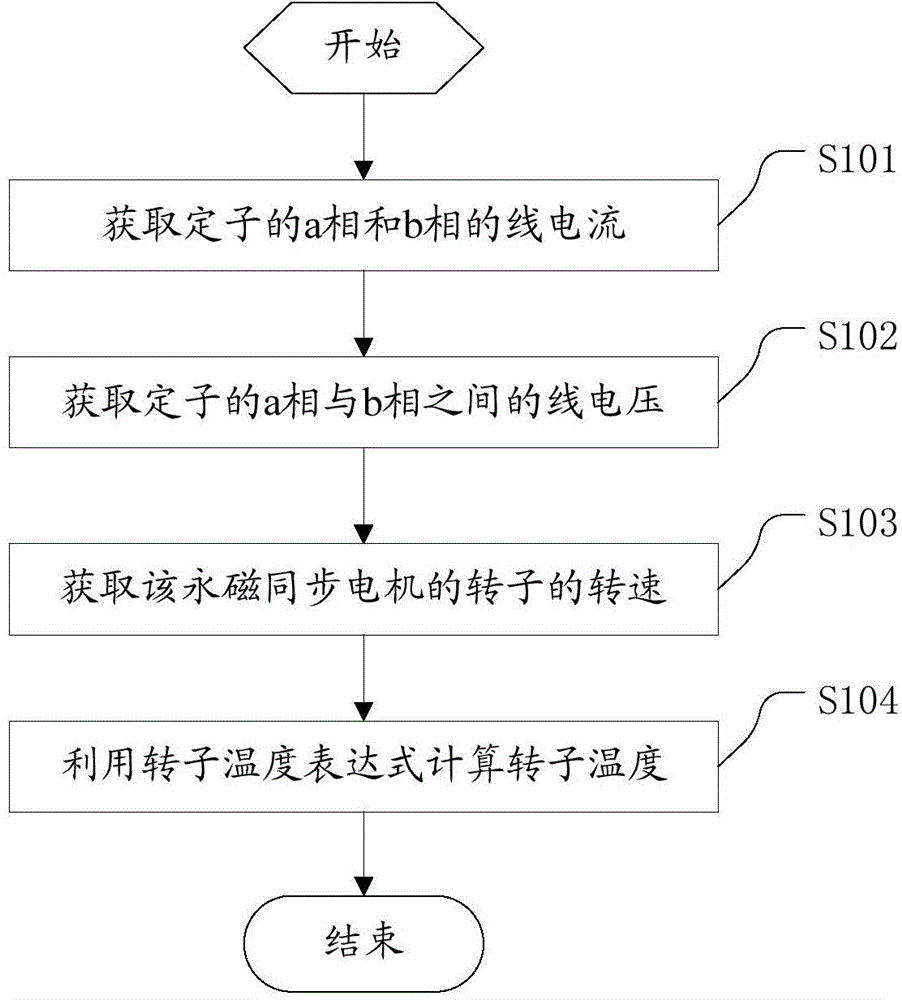
[0061] figure 1 It is a flow chart of a rotor temperature monitoring method for a permanent magnet synchronous motor provided in an embodiment of the present application.

[0062] Firstly, the steady-state mathematical model of permanent magnet synchronous motor is established:

[0063] Current coordinate transformation formula

[0064] i α i β = 1 0 1 / 3 2 / 3 i a ...

Embodiment 2

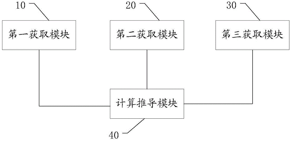
[0123] image 3 A structural diagram of a rotor temperature monitoring system for a permanent magnet synchronous motor provided in another embodiment of the present application.

[0124] like image 3 As shown, the permanent magnet synchronous motor provided in this embodiment includes a first acquisition module 10 , a second acquisition module 20 , a third acquisition module 30 and a calculation and derivation module 40 .

[0125] The first obtaining module 10 is used to obtain the line currents of phase a and phase b of the stator.

[0126] First, the line current of phase a of the stator of the permanent magnet synchronous motor is obtained, and the line current is used as the first line current; the line current of phase b of the stator is obtained, and it is used as the second line current.

[0127] The second obtaining module 20 is used to obtain the line voltage between phase a and phase b of the stator.

[0128] The third obtaining module 30 is used for obtaining th...


PUM


Abstract

The application discloses a rotor temperature monitoring method for a permanent magnet synchronous motor and a system therefor. The rotor temperature monitoring method includes the following steps: an a-phase line current and a b-phase line current of a permanent magnet synchronous motor stator are firstly obtained as a first line current and a second line current, and meanwhile a line voltage between the a phase and the b phase of the stator is obtained; the first line current, the second line current, the line voltage, the inductance parameter of the permanent magnet synchronous motor and the temperature characteristic equation of the permanent magnet of the rotor are put into a preset rotor permanent magnet temperature expression to calculate and obtain a rotor temperature. The rotor temperature monitoring method and the system therefor do not need to embed a temperature sensor in the rotor to monitor the temperature of the rotor permanent magnet, thereby avoiding the problem of low system reliability due to the configuration of the temperature sensor to monitor the temperature of the rotor permanent magnet.

Description

technical field [0001] The present application relates to the field of motor technology, and more specifically, to a rotor temperature monitoring method and system of a permanent magnet synchronous motor. Background technique [0002] In the existing permanent magnet synchronous motor, a temperature sensor must be configured to monitor the temperature of the motor. Different permanent magnet materials will exhibit different temperature characteristics, but in general, the magnetic field strength of a permanent magnet will decrease linearly with the increase of temperature, and increase linearly after the temperature decreases. This linear change of temperature always exists within a certain range, but when the temperature is higher than a critical temperature (also known as Curie temperature), the magnetic field strength of the permanent magnet will decrease sharply or even lose its magnetism, and this process is irreversible, that is When the temperature drops below the Cu...

Claims


Application Information

Patent Timeline
Patent Type & Authority Applications(China)
IPC IPC(8): H02P21/14
CPCG01K7/427H02P2207/05H02P29/67H02P29/662G01K13/08H02P29/66H02P6/08H02P21/14G01R31/343H02K21/00H02K2211/00
Inventor 冯江华尚敬许峻峰文宇良刘雄张朝阳肖磊何亚屏南永辉郑汉锋
Owner CSR ZHUZHOU ELECTRIC LOCOMOTIVE RES INST
Why Eureka
Try Eureka