Spray head for gaseous fire extinguishing equipment having silencing function

A technology of fire extinguishing equipment and spray head, which is applied in the field of spray head with noise reduction function, can solve the problems of cost increase and installation site constraints, and achieve the effect of improving the reduction rate, eliminating the installation site constraints, and preventing noise

Active Publication Date: 2014-11-19
KOATSU CO LTD
View PDF12 Cites 15 Cited by
  • Summary
  • Abstract
  • Description
  • Claims
  • Application Information

AI Technical Summary

Problems solved by technology

) among the above-mentioned technologies that are the cause of the problem, the technology described in Patent Document 1, when the fire extinguishing equipment is to be activated, sets the starting timing of the fire extinguishing equipment and the avoidance measures for preventing the malfunction of the ICT device accompanying the activation of the fire extinguishing equipment The technology that is linked at all times is not a technology aimed at reducing noise
[0013] On the other hand, the technologies described in Patent Documents 2 and 3 are also technologies aimed at reducing noise. However, in order to increase the noise reduction rate, it is necessary to increase the size of the nozzle head, which has problems of restricting the installation place and increasing the cost.
[0014] Furthermore, in this spray head, when the fire extinguishing agent gas is discharged, since the large injection reaction force of the fire extinguishing agent gas is applied to the spray head, it is necessary to make the building with the piping system including the spray head equipped with Sufficient support, at this point, also involves the constraints of the installation site and the problem of rising costs

Method used


Image

  • Spray head for gaseous fire extinguishing equipment having silencing function
  • Spray head for gaseous fire extinguishing equipment having silencing function
  • Spray head for gaseous fire extinguishing equipment having silencing function

Examples


Embodiment Construction

[0062] Next, embodiments of the spray head having a noise reduction function for gas fire extinguishing equipment according to the present invention will be described with reference to the drawings.

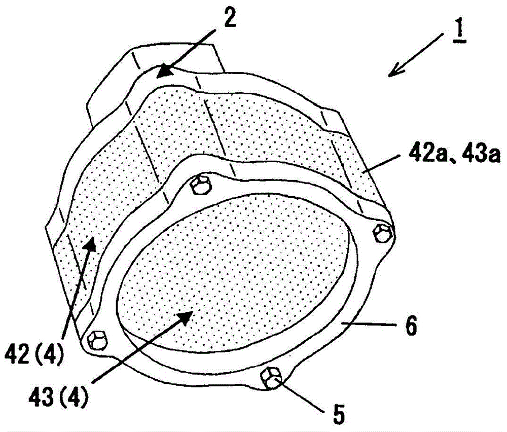
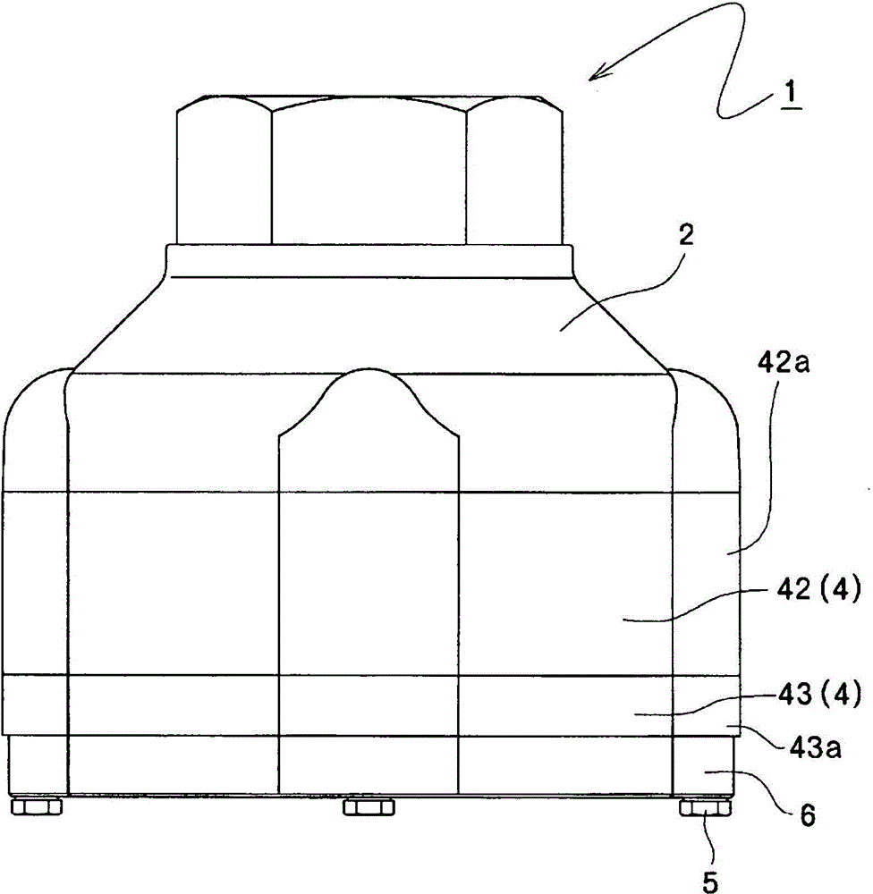
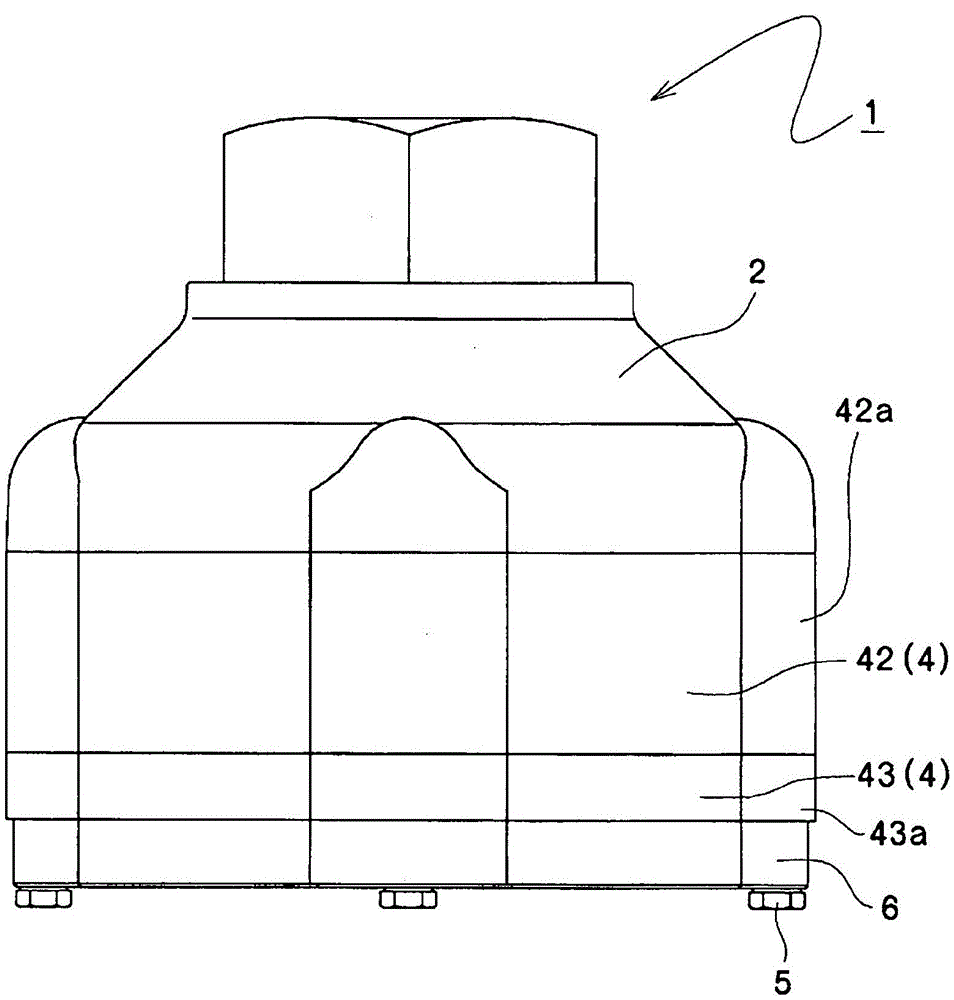
[0063] Figure 1 to Figure 6 It shows the first embodiment of the spray head with noise reduction function for the gas fire extinguishing equipment of the present invention.

[0064] The spray head 1 with a sound-absorbing function for gas fire extinguishing equipment is a spray head provided for discharging fire extinguishing agent gas to a fire extinguishing target area in gas fire extinguishing equipment using fire extinguishing agent gas. (Illustration omitted) connected head main body 2, orifice plate 3 with a plurality of orifice holes 31 formed on the stepped portion 21 formed in the internal space of the head main body 2, detachably arranged A block-shaped sound-absorbing member 4 made of a gas-permeable porous material arranged at the outlet of the orifice 31 and an ann...


PUM


Abstract

[Problem] To present an injection head for gas-type fire exchanger using an injection head of a small size, capable of enhancing the noise reduction rate, and lowering the injection reaction of the fire-extinguishing gas applied to the injection head at the time of release of the fire-extinguishing gas. [Solving Means] An injection head 1 having silencing means installed for releasing a fire-extinguishing gas in a fire-extinguishing area in the gas type fire extinguisher using a fire-extinguishing gas, in which the silencing means includes silencing members 4 of block shapes made of a porous material capable of passing a gas disposed at an outlet of the orifice 31, and a one-side end face of the silencing member 4 is disposed in contact with the injector head main body 2, and a peripheral face and an other-side end face of the silencing member 4 are opened to the atmosphere except for the portion contacting with a ring member 6 for fixing the silencing member 4 to the injection head main body 2 by way of a bolt 5.

Description

technical field [0001] The present invention relates to a spray head installed on the ceiling, wall, etc. in order to discharge the fire extinguishing agent gas to the fire extinguishing target area in the gas fire extinguishing equipment using fire extinguishing agent gas such as nitrogen, carbon dioxide, fluoride, etc. A spray head with a noise reduction function for gas fire extinguishing equipment that eliminates the noise generated when spraying gas. Background technique [0002] In gas fire extinguishing equipment that uses fire extinguishing agent gases such as nitrogen, carbon dioxide, and fluoride, if the gas fire extinguishing equipment operates during fire extinguishing, the fire extinguishing agent gas is discharged so that within about 1 minute (in fluoride fire extinguishing agent gas) In the case of 10 seconds), the fire extinguishing agent gas concentration in the fire extinguishing target area reaches the fire extinguishing concentration. [0003] At this t...

Claims


Application Information

Patent Timeline
Patent Type & Authority Applications(China)
IPC IPC(8): A62C31/02B05B1/00
CPCB05B1/00A62C31/02B05B1/002
Inventor 薮下真大井上康史
Owner KOATSU CO LTD
Why Eureka
Try Eureka