Water-saving-valve-controlled drip irrigation tank

A technology of water-saving valves and water valves, applied in watering devices, climate change adaptation, gardening, etc., can solve the problems of unstable operation, high failure rate, and unsatisfactory reliability of drip irrigation tanks, and achieve a high degree of intelligent interface, Good anti-blocking performance, uniform and stable water discharge

Inactive Publication Date: 2014-11-26
HUBEI FOR LONG PIPE TECH CO LTD
View PDF3 Cites 12 Cited by
  • Summary
  • Abstract
  • Description
  • Claims
  • Application Information

AI Technical Summary

Problems solved by technology

[0003] The purpose of the present invention is to solve the above-mentioned six problems existing in the traditional drip irrigation system, and at the same time solve the prob

Method used


Image

  • Water-saving-valve-controlled drip irrigation tank
  • Water-saving-valve-controlled drip irrigation tank

Examples


example 1

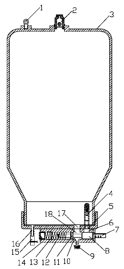
[0054] Example 1: Structure one of the present invention. It has a closed tank 3, a vent check valve 2 is installed on the top of the tank 3, and a water inlet 5 and a water outlet 17 are provided at the bottom of the tank 3. Its characteristics are : A water inlet check valve 4 is installed buttly inside the water inlet 5, and an inlet and outlet linkage water valve is installed at the bottom of the tank 3. The inlet and outlet linkage water valve has a valve body 14 with a piston cavity 10 installed in the valve body 14 There are a piston 8 and a compression spring 13. A water inlet pipe 7 is provided on the valve body 14 at one end of the piston 8 to communicate with the piston cavity 10; and a water supply port 5 is provided on the valve body 14 to communicate with the water inlet 5 at the bottom of the tank 3. There is a transitional water port 18 communicating with the water outlet 17 at the bottom of the tank body 3; a drip distributor 9 is also installed on the valve bod...

example 2

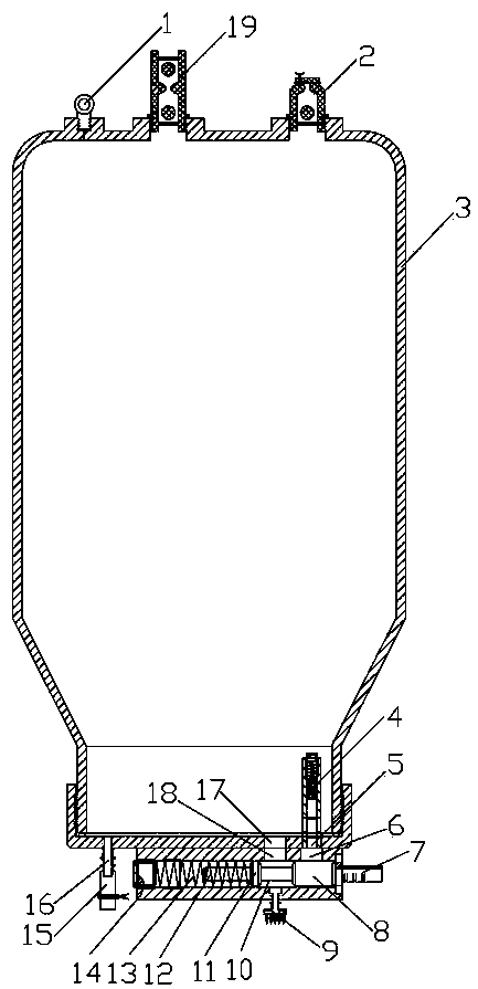
[0059] Example 2: See figure 2 The basic structure of the second structure of the present invention is the same as that of Example 1, except that an air-controlled regulating valve 19 is also installed on the top of the tank body to facilitate the adjustment of the dripping volume.


PUM


Abstract

The invention relates to agricultural irrigation devices, in particular to a water-saving-valve-controlled drip irrigation tank. The water-saving-valve-controlled drip irrigation tank is provided with a closed tank body, a ventilation overflow stop valve is arranged at the top of the tank body, and a water inlet and a water outlet are formed in the bottom of the tank body. The water-saving-valve-controlled drip irrigation tank is characterized in that a water inlet one-way valve is arranged on the inner side of the water inlet in a butt joint mode, an in-out linkage water valve is arranged at the bottom of the tank body and provided with a valve body, a piston cavity provided with a piston and a compression spring is arranged in the valve body, and a water inlet pipe is installed at the end, close to the piston, of the valve body to be communicated with the piston cavity. A water supply opening is formed in the valve body to be communicated with the water inlet in the bottom of the tank body, and a transition water opening is formed to be communicated with the water outlet in the bottom of the tank body. A water drip distribution device is further arranged on the valve body and communicated with the piston cavity. The water-saving-valve-controlled drip irrigation tank overcomes the defects that blocking occurs easily when drip irrigation is conducted through a water dropper, water yield cannot be adjusted, the water dropper is complex in structure, high in manufacturing cost and short in service life, and a system is large in power consumption. Meanwhile, the water-saving-valve-controlled drip irrigation tank is more stable and more reliable in work, low in failure rate and wide in agricultural crop irrigation application range.

Description

technical field [0001] The invention relates to an agricultural irrigation device, in particular to a water-saving valve-controlled drip irrigation tank. Background technique [0002] An important branch of modern agricultural irrigation is the irrigation technology system, which includes a water pump station, main water pipe, water distribution pipe and multiple special drippers installed on the water distribution pipe. The structure of this dripper is very complicated and the manufacturing precision The requirements are high. At present, the drippers used in China mainly rely on imports. There are a few imitations in China, but the technology is not good enough. The problems existing in the existing special drippers at home and abroad are: ⑴The drippers are easy to block; ⑵Large power consumption and high operating costs High; ⑶ uneven irrigation volume of drippers; ⑷ short service life; ⑸ slow response of the system to the adjustment of crop irrigation system; ⑹ high prod...

Claims


Application Information

Patent Timeline
IPC IPC(8): A01G25/02
CPCY02A40/22
Inventor 吴思啸苏睿吴琪
Owner HUBEI FOR LONG PIPE TECH CO LTD
Why Eureka
Try Eureka