Minimally invasive bone fetcher

A bone chip and collection container technology, applied in the field of minimally invasive bone harvester, can solve problems such as easy sequelae, patient injury, and inconvenience of bone harvesting, and reduce the risk of injury to the lateral femoral cutaneous nerve. small effect

Active Publication Date: 2014-11-26
李万里
View PDF7 Cites 10 Cited by
  • Summary
  • Abstract
  • Description
  • Claims
  • Application Information

AI Technical Summary

Problems solved by technology

[0003] The present invention mainly solves the technical problems of large incision in the original bone harvesting method, inconvenient bone harvesting, easy injury to the patient, and easy sequelae; it provides a minimally invasive bone harvester, which only needs tiny skin incisions and tiny skin incisions. The bone window is ground into bone chips and then taken out. It is easy to operate and fast to take the bone, which greatly reduces the harm to the patient during the bone taking process, avoids the occurrence of sequelae, and improves the safety of the bone taking.

Method used


Image

  • Minimally invasive bone fetcher
  • Minimally invasive bone fetcher
  • Minimally invasive bone fetcher

Examples


Embodiment 1

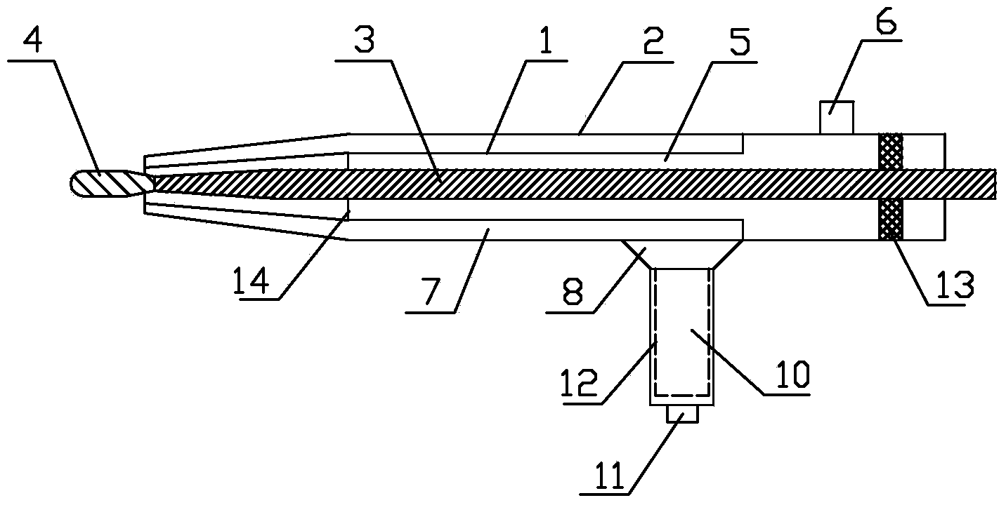
[0027] Embodiment 1: the minimally invasive bone extractor of the present embodiment, such as figure 1As shown, it includes a sleeve 20, a connecting rod 3 located on the axis of the sleeve and a drill bit 4 connected to the front end of the connecting rod 3. The sleeve 20 adopts a double-layer sleeve, and the double-layer sleeve includes a connected inner layer sleeve Cylinder 1 and outer sleeve 2, inner sleeve 1 and outer sleeve 2 are arranged coaxially, inner sleeve 1 has a shoulder, the inner sleeve in front of the shoulder is thinner, and the thinner inner sleeve There is an outer sleeve 2 connected to the outer sleeve of the sleeve, and the inner sleeve behind the shoulder is thicker. There is a water inlet 6 on the thicker inner sleeve, and the water inlet is set vertically upward. The inner sleeve 1 and the connecting rod 3 A water inlet channel 5 is formed between them, and the water inlet channel 5 communicates with the water inlet 6. A discharge channel 7 is formed ...

Embodiment 2

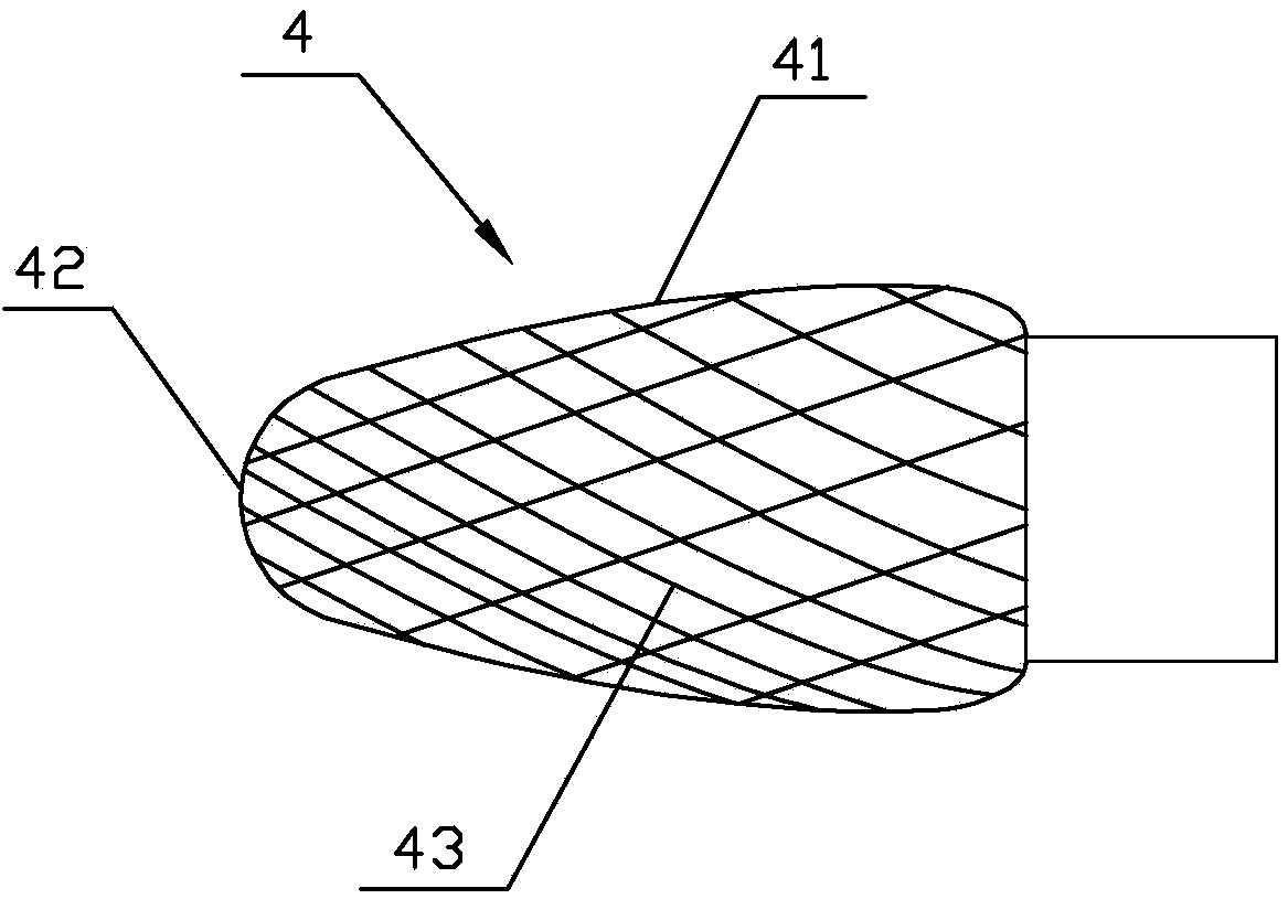
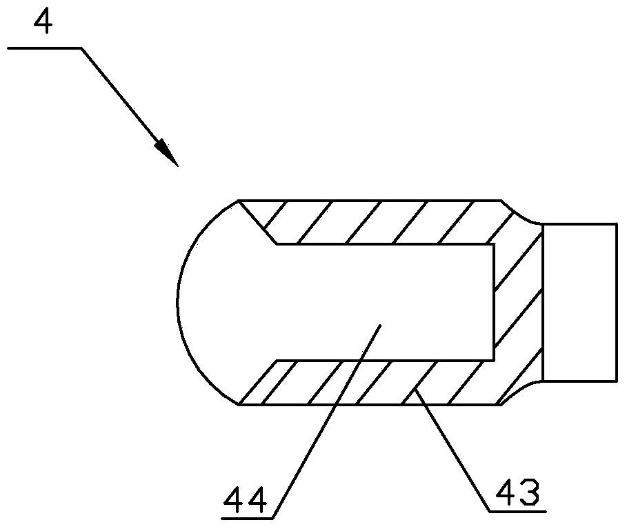
[0029] Embodiment 2: the minimally invasive bone extractor of the present embodiment, such as image 3 As shown, the front end of the drill bit 4 is a spherical surface 42, and the side of the drill bit 4 has three strip-shaped grooves 44 axially arranged, and the three grooves are evenly distributed along the circumferential surface of the drill bit, and the rear end of the groove 44 Near the rear end of the drill bit 4 , the front end of the groove 44 is open at the front end of the drill bit 4 , and the side of the drill bit 4 except the groove 44 has a blade 43 which is arranged obliquely. All the other structures are with embodiment 1.

[0030] The groove mouth is equivalent to the blade set in the axial direction, which is powerful and convenient for grinding drills. Combined with the blade set at an angle, it can quickly grind down the bone debris. Important tissue structure of the patient.

Embodiment 3

[0031] Embodiment 3: the minimally invasive bone extractor of the present embodiment, such as Figure 4 As shown, the rear end of the connecting rod 3 is connected to the rotary drive device. In the present embodiment, the rotary drive device is a small hand-held electric drill 15, and the rear end of the connecting rod 3 is connected to the motor 151 in the hand-held electric drill 15. The rear end of the layer sleeve (that is, the rear end of the thicker inner layer sleeve) is clamped with the shell of the hand-held electric drill 15. A battery for powering the motor is installed in the handle 152 of the hand-held electric drill 15, and a switch 153 for controlling the power on and off of the motor is installed on the handle 152 of the hand-held electric drill 15. All the other structures are with embodiment 1.

[0032] The doctor can operate it by holding the handle of the hand-held electric drill, and can control the switch at the same time when holding it. It is labor-sa...


PUM


Abstract

The invention relates to a minimally invasive bone fetcher. The minimally invasive bone fetcher comprises a sleeve, a connecting rod arranged in the sleeve in a penetrating mode and an abrasive drilling bit connected to the front end of the connecting rod. A water inlet channel and a discharge channel are formed in the sleeve. The sleeve is provided with a water inlet communicated with the water inlet channel and a discharge port communicated with the discharge channel. The discharge port is provided with a bone fragment collection container connected with a negative pressure suction device. The head end of the bone fetcher is small, a bone substance is abraded into bone fragments to be taken out through a minute skin incision and a minute bone window, then a minimally invasive bone fetching operation is rapidly completed, the risk of injuring the lateral femoral cutaneous nerve is greatly lowered, pain in the bone fetching area is alleviated, the occurrence rate of factures or ventral hernia is lowered, and the postoperative infection rate of the bone substance supply area is greatly decreased as well. The minimally invasive bone fetcher is easy to operate, saves labor and valuable operation time and brings great convenience to the bone fetching operation.

Description

technical field [0001] The invention relates to a medical device, in particular to a minimally invasive bone extractor with high bone extraction speed and less harm to patients. Background technique [0002] Bone grafting is to transplant bone tissue to the bone defect in the patient's body that needs to be strengthened or fused through surgery. It is often used for bone defect, fracture nonunion, bone disease or cavity filling after bone tumor curettage, spine and joint fusion, etc. Condition. The commonly used autologous bone graft has many advantages, such as good histocompatibility, no graft rejection, strong osteoinductive effect, etc., and has a good effect of promoting bone fusion. Commonly used bone harvesting sites for autologous bone transplantation include the ilium, tibia, upper fibula, and ribs. Autologous bone transplantation is to remove the bone from these parts of the patient's own body, and then return to the patient's bone defect for transplantation after...

Claims


Application Information

Patent Timeline
Patent Type & Authority Applications(China)
IPC IPC(8): A61B17/16A61B17/56
CPCA61B17/00234A61B17/1604A61B17/1615A61B17/1635A61B2017/1602
Inventor 李万里
Owner 李万里
Why Eureka
Try Eureka