Single-box vacuum oil immersion device and oil immersion method thereof

A technology of vacuum immersion and tank, which is applied in the field of vacuum oil immersion device and its oil immersion, which can solve the problems of large labor load of lubricating oil, numerous connecting pipes, waste of lubricating oil, etc., and achieves simple structure, low test cost, and oil immersion easy effect

Active Publication Date: 2014-11-26
合肥波林新材料股份有限公司
View PDF10 Cites 8 Cited by
  • Summary
  • Abstract
  • Description
  • Claims
  • Application Information

AI Technical Summary

Problems solved by technology

This prior art vacuum oil immersion device, because it adopts two casings, causes complex structure, various connecting pipes, heavy device, relatively large volume, is generally suitable for industrial use, and one-time use lubricating oil reaches 200Kg, is applicable to The production of parts in large quantities; But, for the parts that are in the experimental stage, especially to the test of lubricating oil, it is necessary to prepare different types of lubricating oil, and adopt the vacuum device in the prior art, the amount of lubricating oil that needs to be prepared at one time is very large If the test result of the prepared lubricating oil is unsatisfactory, a large amount of lubricating oil may be wasted; and the labor load is relatively large when changing the lubricating oil
In addition, vacuum oil immersion sometimes needs to heat the lubricating oil. For existing industrial vacuum oil immersion devices, even if the number of parts to be oiled is small or there are only a few test samples, a large amount of lubricating oil needs to be heated. All the oil is heated to the set temperature, resulting in waste of resources

Method used


Image

  • Single-box vacuum oil immersion device and oil immersion method thereof
  • Single-box vacuum oil immersion device and oil immersion method thereof
  • Single-box vacuum oil immersion device and oil immersion method thereof

Examples


Embodiment 1

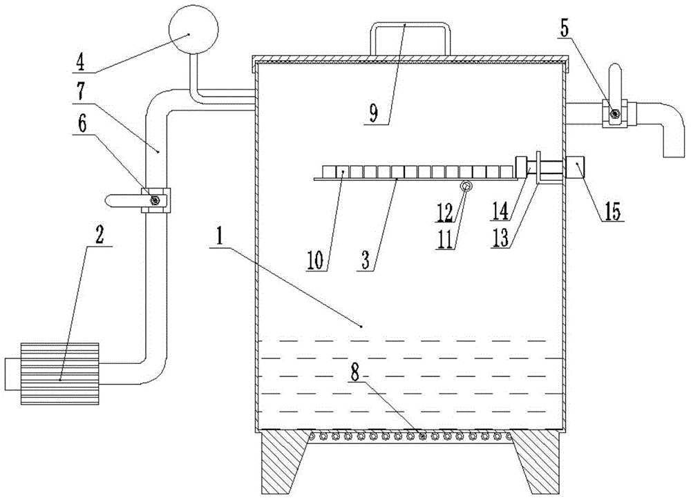
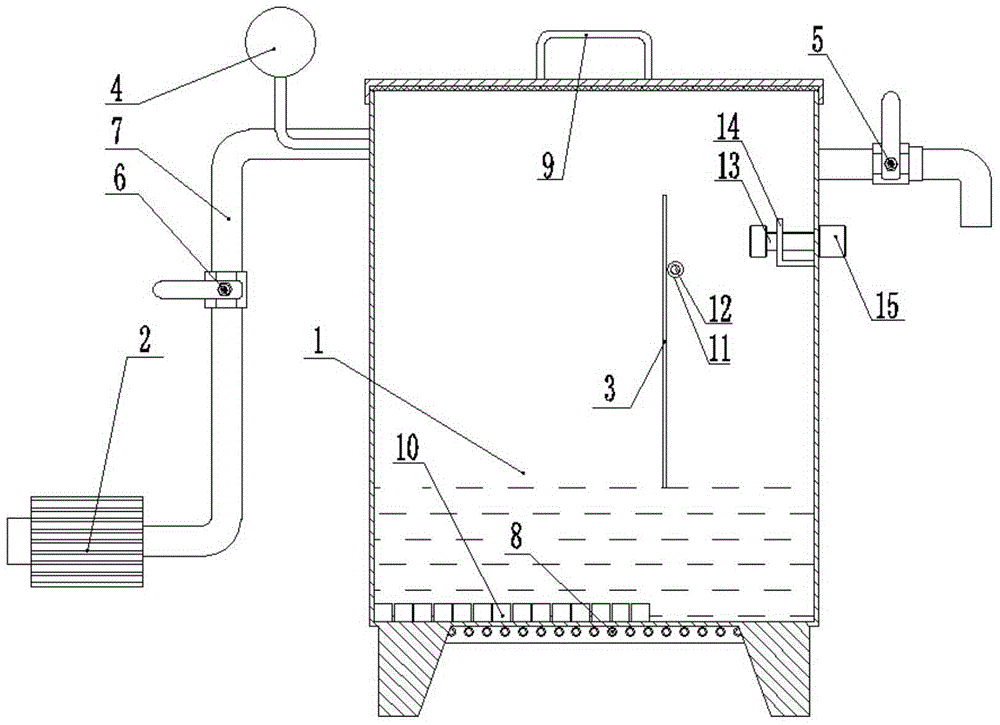
[0028] figure 1 It is a schematic diagram before oil immersion when the single box vacuum oil immersion device of the present invention uses the L bracket tilting mechanism; figure 2 It is a schematic diagram of oil immersion when the single box vacuum oil immersion device of the present invention uses the L bracket tilting mechanism; figure 1 , figure 2 The present invention is further described.

[0029] A single-box vacuum oil immersion device of the present invention includes a closed oil immersion tank 1 composed of a tank cover and a box body, a vacuum pump 2 connected to the oil immersion tank 1 with a vent pipe 7, and a storage board located in the oil immersion tank 3, and a tilting mechanism for tilting the shelf 3 or a lifting mechanism for lifting the shelf 3; a vacuum gauge 4 and an air release valve 5 are arranged on the box cover or on the upper side wall of the box; A pressure maintaining valve 6 is arranged on the ventilation pipe 7; the tilting mechanism...

Embodiment 2

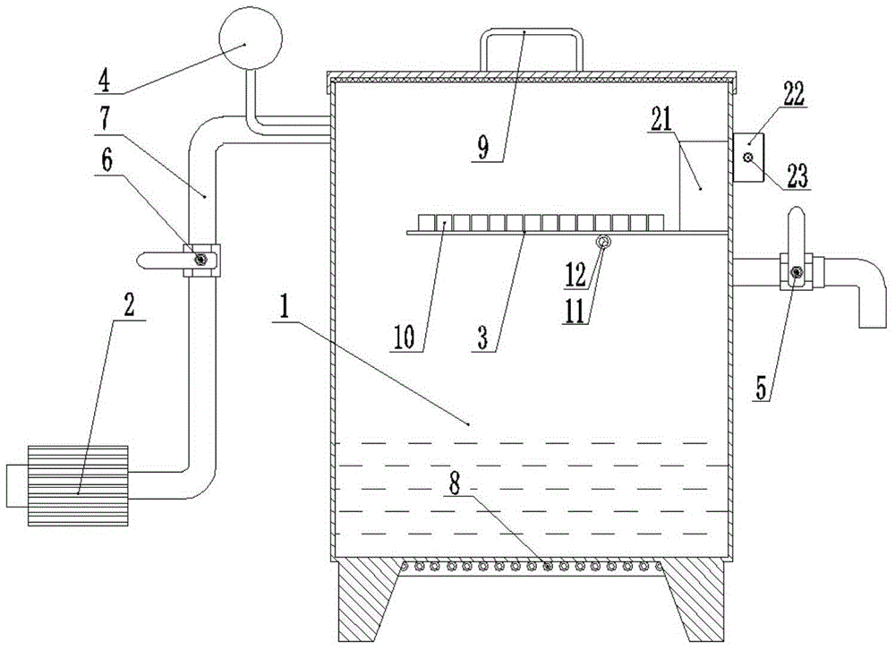
[0039] see image 3 with Figure 4 , the structural form of the single-box vacuum oil immersion device in this embodiment is: a cam tilting mechanism is used to replace the L bracket tilting mechanism in Embodiment 1, and the tilting mechanism is located at the top of the box, including the end face welded on the box. Rotating ring 11, rotating shaft 12, cam 21, runner 22 fixedly arranged on the storage board 3, and handle 23 welded or threaded with the rotating wheel 22; the inner hole gap between the rotating shaft 12 and the rotating ring 11 Cooperate; the runner 22 and the handle 23 are located outside the box body, the runner 22 is connected with the cam 21 through the connecting shaft passing through the side wall of the box body, and a Sealing ring; when the boundary point of the cam 21 farthest from the base circle is in contact with the storage board 3, the storage board 3 is horizontal.

[0040] The steps of the oil immersion process using the device described in t...

Embodiment 3

[0044] see Figure 5 , the structural form of the single box vacuum oil immersion device in the present embodiment is: use the runner lifting mechanism to replace the L bracket tilting mechanism in embodiment 1, the lifting mechanism is located at the top of the casing, including lifting rope 31, lifting shaft 32, Runner 22, and the handle 23 that is welded or threaded with runner 22, one end of lifting rope 31 is tied on the storage board 3, and the other end is wound on the lifting shaft 32, and the two ends of lifting shaft 32 are fixed on the case by rotating connection. On the body, the runner 22 and the handle 23 are located outside the box body, the runner 22 is connected with the lifting shaft 32 through the connecting shaft passing through the side wall of the box body, and a sealing ring is arranged between the connecting shaft and the side wall of the box body , an oil hole is provided on the storage board 3 .

[0045] Use the oil immersion process step of this dev...


PUM


Abstract

The invention discloses a single-box vacuum oil immersion device for powder metallurgy parts and an oil immersion method thereof. The single-box vacuum oil immersion device and the oil immersion method thereof are characterized in that the oil immersion device comprises an airtight oil immersion box which is composed of a box cover and a box body, a vacuum pump which is connected with the oil immersion box through an air duct, an object storing plate placed in the oil immersion box, and a tilting mechanism used for tilting the object storing plate or a lifting mechanism used for lifting the object storing plate; a vacuum meter and a deflation valve are arranged on the box cover or the upper portion of the side wall of the box body, a pressure retaining valve is arranged on the air duct, the tilting mechanism or the lifting mechanism is fixedly arranged on the box body, and a heating pipe is arranged at the bottom of the box body. The single-box vacuum oil immersion device is easy to manufacture, low in weight, convenient to operate, small in testing cost and high in testing efficiency. By the adoption of the single-box vacuum oil immersion device and the oil immersion method thereof, compared with an existing vacuum device, the oil immersion effect is the same.

Description

technical field [0001] The invention relates to a vacuum oil immersion device and an oil immersion method thereof, in particular to a vacuum oil immersion device and an oil immersion method for powder metallurgy parts. Background technique [0002] Vacuum oil immersion of powder metallurgy parts is to put the parts to be oiled into a vacuumable container. Firstly, vacuum the container to make the parts in a certain vacuum state. The oil storage tank is injected into the vacuum container. Since the parts are in a negative pressure environment, the injected lubricating oil will enter the gaps of the parts, and the speed of oil immersion is relatively fast, and the final oil content of the parts is relatively high. The vacuum oil immersion device in the prior art includes an oil storage tank and an oil immersion tank, or includes two parts equivalent to the oil storage tank and the oil immersion tank, as disclosed in the technical solution disclosed in the utility model patent ...

Claims


Application Information

Patent Timeline
IPC IPC(8): B22F3/26
CPCB22F3/26
Inventor 李其龙徐伟
Owner 合肥波林新材料股份有限公司
Why Eureka
Try Eureka