High-efficiency water treatment device
A water treatment device and high-efficiency technology, applied in water/sewage multi-stage treatment, water/sludge/sewage treatment, chemical instruments and methods, etc. Mountain and stream water treatment and other issues to achieve the effect of reducing energy consumption
- Summary
- Abstract
- Description
- Claims
- Application Information
AI Technical Summary
Problems solved by technology
Method used
Image
Examples
Embodiment 1
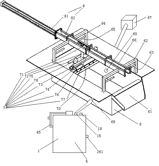
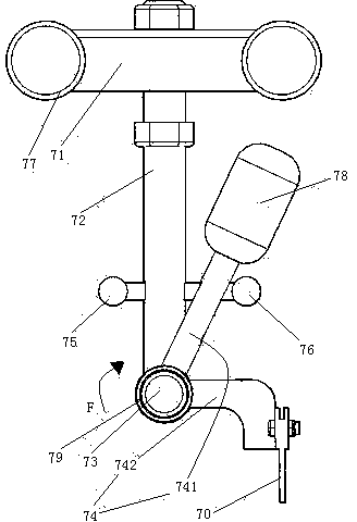
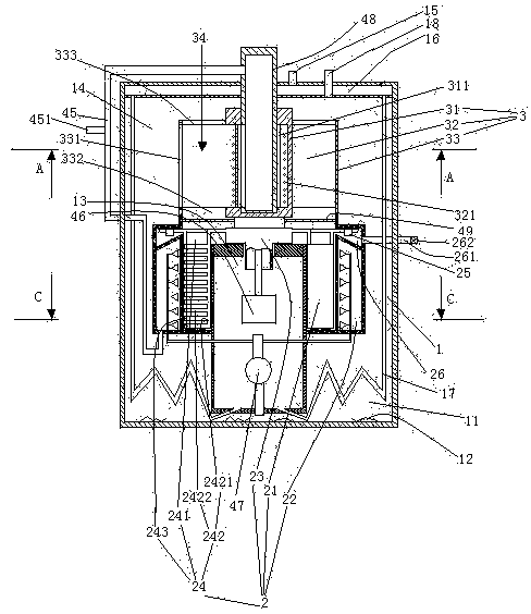
[0029] Embodiment one, see figure 1 , a high-efficiency water treatment device, including suspended matter separation tank 6, scraper 70, cylinder 8, scraper hanger 7, raw water sedimentation tank 67, pure water mechanism 5 and slide rail 66.
[0030] The front end of the suspended matter separation tank 6 is provided with a slag outlet 61 and a front support frame 62 of the slide rail. A liquid outlet 69 and a liquid inlet 60 are provided in the middle of the suspension separation tank 6 . The width of the slag outlet 61 (the left and right direction in the figure is the width direction) is equal to the width of the inner space of the suspended matter separation tank 6 . The front support frame 62 of the slide rail is provided with a scraper lifting trigger 63 . The scraper lifting trigger 63 is a stopper with a rod-shaped structure. There are two scraper lifting triggers 63 . Two scraper lift triggers 63 are distributed along the left and right directions. The rear end ...
Embodiment 2
[0053] Embodiment two, the difference with embodiment one is:
[0054] see Figure 7 , also includes refueling device 9. The refueling device 9 includes an oil storage tank 91 , an oil outlet channel 92 , a membrane rupture rod 93 , a corrosive liquid storage tank 94 , a periodic rotting buoy 95 and a guide rod 96 .
[0055] The oil storage tank 91 is connected together with the regularly putrefying formula buoy 95 by a connecting rod 98 . The connecting rod 98 and the regular rotting buoy 95 are detachably connected together by bolts. The oil storage tank 91 includes at least two cavities 911 which in this embodiment are four cavities 911 which are sequentially sleeved and fixed together. Lubricating oil is housed in the cavity 911 (not shown in the lubricating oil figure). The lower wall of the cavity 911 is provided with an oil outlet 912 . The oil outlet 912 is sealed and connected with a sealing membrane 913 . A total of 4 oil outlets 912 of the 4 cavities are locate...
PUM
 Abstract
Description
Claims
Application Information
 - R&D
- Intellectual Property
- Life Sciences
- Materials
- Tech Scout
- Unparalleled Data Quality
- Higher Quality Content
- 60% Fewer Hallucinations
Browse by: Latest US Patents, China's latest patents, Technical Efficacy Thesaurus, Application Domain, Technology Topic, Popular Technical Reports.
© 2025 PatSnap. All rights reserved.Legal|Privacy policy|Modern Slavery Act Transparency Statement|Sitemap|About US| Contact US: help@patsnap.com


