Energy feedback type damper combining piezoelectric ceramic and magnetorheological fluid

A technology of magnetorheological fluid and piezoelectric ceramics, applied in liquid shock absorbers, shock absorbers, shock absorbers, etc., can solve the problems of limited use area, ineffective use of electric energy, waste and other problems

Active Publication Date: 2014-11-26
HUAQIAO UNIVERSITY
View PDF9 Cites 21 Cited by
  • Summary
  • Abstract
  • Description
  • Claims
  • Application Information

AI Technical Summary

Problems solved by technology

At present, some new damping materials mainly include piezoelectric smart materials, shape memory alloys, magnetorheological fluids, electrorheological fluids, etc. Among them, piezoelectric ceramics are characterized by their large output, fast response, no electromagnetic interference, low energy consumption, Good electromechanical coupling characteristics, easy control and other advantages have been widely researched and applied in the field of vibration isolation and vibration reduction in aerospace, automotive engines, micro-motion platforms, ...

Method used


Image

  • Energy feedback type damper combining piezoelectric ceramic and magnetorheological fluid
  • Energy feedback type damper combining piezoelectric ceramic and magnetorheological fluid
  • Energy feedback type damper combining piezoelectric ceramic and magnetorheological fluid

Examples


Embodiment Construction

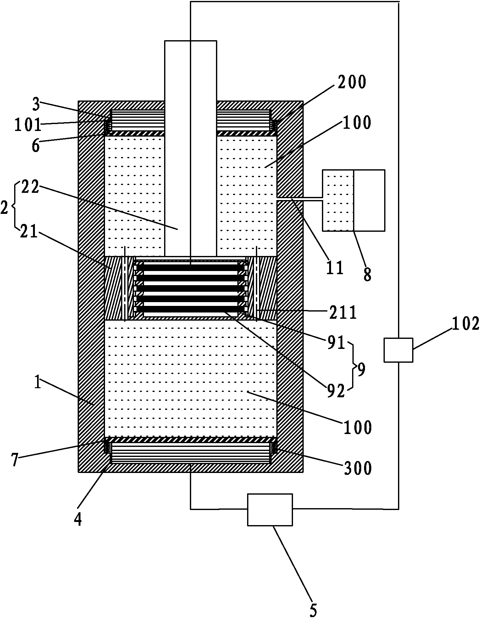
[0029] The energy-feeding damper combined piezoelectric ceramics and magnetorheological fluid of the present invention, such as Figure 1-3 As shown, it includes a cylinder 1, a piston rod 2, an upper piezoelectric generating unit 3 and a lower piezoelectric generating unit 4 inside the cylinder 1, and an electric energy extraction and storage unit 5 and a control unit outside the cylinder 1; :

[0030] The cylinder body 1 is a hollow cylindrical structure with closed upper and lower ends. The piston rod 2 has a plug body 21 and a rod body 22 vertically connected to the upper surface of the plug body 21. The plug body 21 is located in the cylinder body 1, and Sealed with the inner side wall of the cylinder body 1 , the rod body 22 is erected in the cylinder body 1 , and the upper end of the rod body 22 protrudes tightly out of the upper surface of the cylinder body 1 .

[0031] The upper piezoelectric power generation unit 3 is set outside the upper end of the rod body 22. Th...


PUM


Abstract

The invention discloses an energy feedback type damper which can combine piezoelectric ceramic and magnetorheological fluid, wherein the energy feedback type damper can supply electric energy which is generated by piezoelectric electricity generation units due to vibration to the magnetorheological fluid for shock absorption. The energy feedback type damper comprises a cylinder body, a piston rod, the upper piezoelectric electricity generation unit, the lower piezoelectric electricity generation unit, an electric energy extraction and storage unit, a pressure sensor and a controller. The upper piezoelectric electricity generation unit is installed outside a rod body in a sleeved mode. An upper partition plate is arranged below the upper piezoelectric electricity generation unit in an overlapping mode. The lower piezoelectric electricity generation unit is arranged on the inner bottom surface of the cylinder body. A lower partition plate is arranged on the lower piezoelectric electricity generation unit in an overlapping mode. An upper magnetorheological fluid chamber containing magnetorheological fluid is formed between the upper partition plate and a piston body. A lower magnetorheological fluid chamber containing magnetorheological fluid is formed between the piston body and the lower partition plate. The piston body is provided with a plurality of throttling holes. An excitation coil mechanism is installed in the piston body. The upper piezoelectric electricity generation unit and the lower piezoelectric electricity generation unit are connected with the electric energy extraction and storage unit. The pressure sensor is connected with the controller. The electric energy extraction and storage unit is connected with the excitation coil mechanism through the controller. The pressure sensor is installed on the upper partition plate.

Description

technical field [0001] The invention relates to a damper, in particular to an energy-feeding damper based on the combination of piezoelectric ceramics and magnetorheological fluid. Background technique [0002] The reciprocating motion of an object along a straight line or arc with the center position (balance position) as the reference under the action of external force is called mechanical motion, or vibration for short. Harmful vibrations in industrial production and daily life have affected industrial production and people's lives. [0003] Generally speaking, the hazards of vibration mainly include the following aspects: 1) It affects the service life of the mechanical system and its parts; 2) It affects the precision of the structure and system operation; 3) It affects the comfort of people's production and life, resulting in noise pollution. In addition, unnecessary vibration will cause more harm. For example, in the field of civil engineering, the vibration of build...

Claims


Application Information

Patent Timeline
IPC IPC(8): F16F9/32F16F9/53F16F9/19
Inventor 杨帆高红凯夏明博彭正
Owner HUAQIAO UNIVERSITY
Why Eureka
Try Eureka