
Bionic facetted eye imaging target positioning system

A bionic compound eye, target positioning technology, applied in the field of target detection, can solve problems such as high performance requirements, immature processing technology, heavy weight, etc. The effect of location tracking

Inactive Publication Date: 2014-11-26
CHANGCHUN UNIV OF SCI & TECH
View PDF4 Cites 24 Cited by
  • Summary
  • Abstract
  • Description
  • Claims
  • Application Information

AI Technical Summary

Problems solved by technology

Although wide-angle lenses and fisheye lenses can effectively increase the field of view of the optical system, they are expensive, difficult to install and adjust, heavy in weight, and their complex structures require high material performance in certain wavebands, such as infrared wavebands.
In recent years, with the rapid development of bionic optics, the problem of the uniqueness of the optical axis has been solved by using the imaging principle of insect compound eyes, which can effectively expand the field of view of the system, but the working distance of the microlens system is short and the processing technology is not yet mature. , which greatly limits the application of compound eye imaging technology

Method used


Image

  • Bionic facetted eye imaging target positioning system
  • Bionic facetted eye imaging target positioning system
  • Bionic facetted eye imaging target positioning system

Examples


Embodiment Construction

[0020] The present invention will be described in further detail below in conjunction with accompanying drawings and examples.

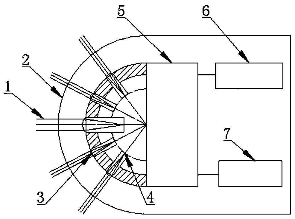
[0021] 2. If figure 1 As shown, the system is mainly composed of protective glass 2, sub-eye large-aperture compound eye optical system 3, curved surface distributed detector array 4, signal processing system based on neural network 5, servo control system 7, and system machine control signal processing system 7 Among them, the large-aperture compound-eye optical system 3, as a key component to realize a series of special functions, is mainly responsible for collecting the optical information 1 of the target and the background, and focusing the incident light onto the detector array 4 distributed on the curved surface for imaging. The signal processing system 5 not only optically preprocesses the image information, the signal processing system adopts the neural network processing method, and the computer can realize the rapid identification of the ta...


PUM


Abstract

The invention discloses a novel bionic facetted eye imaging target positioning system, and belongs to a target detection field. The bionic facetted eye imaging target positioning system comprises protect glass, a large aperture facetted eye optical system, a curved surface distributed detector array, a computer neural network signal processing system, a servo control system, an engine control signal processing system, a supporting structure and a shell. The compound eye optical system, as an optical information acquisition system of the system, focuses incident light on the curved surface distributed detection array for imaging; the signal processing system not only pre-treats the optical image information; the signal processing system employs a neural network treatment manner and a computer carries out repeated training on an established target information database, so as to realize rapid identification of a target and outputs the information to the servo control system in a digital signal form; the servo control system treats and analyzes the input digital signal to obtain current relative position information of the target and output the current relative position information of the target to the engine control signal processing system in a feedback signal for; and the engine control signal processing system adjusts a gesture of the system according to the feedback signal to realize precise positioning and tracking. The system is simple and compact in structure and low in cost, and has the characteristics of wide detection scope, high resolution, high identification probability and accurate positioning.

Description

technical field [0001] The invention belongs to the technical field of target detection, and in particular relates to a novel bionic compound eye imaging target positioning system which uses a bionic insect compound eye optical system to collect optical image information of a target and is capable of transmitting, processing and controlling the information. Background technique [0002] Target detection and recognition technology is the core technology of automatic monitoring and tracking system. With the continuous advancement of technology and the increasingly complex working environment, its performance requirements are constantly improving. Optical precision guidance technology, as an important precision guidance technology, has the advantages of high resolution, easy imaging, high measurement accuracy without multipath effect, good concealment, light weight and small size. The novel bionic compound eye imaging target positioning system involved in the present invention ...

Claims


Application Information

Patent Timeline
Patent Type & Authority Applications(China)
IPC IPC(8): G01C21/00G06N3/02
CPCG01C21/00
Inventor 付跃刚董正超赵雨时赵宇李妍冬
Owner CHANGCHUN UNIV OF SCI & TECH
Learn More